
1. Shimmer Dock
Shimmer3R: Shimmer3R has the same external connector as Shimmer3, and works in the Dock in the same way: charging, SD card access, configuration and firmware update. It also has its own USB-C socket, on its side, which presents a serial port and the SD card to a PC directly; see Shimmer3R hardware in the Shimmer3/3R User Manual.
The Shimmer Dock (referred to as the Dock from here on) is a multi-purpose device which can provide three primary functions, as described in more detail throughout this section:
Charging the Shimmer
microSD Card access
Programming the Shimmer
Whilst there have been several Dock design iterations, the current Dock is the Shimmer Dock v3, which is best identified by a square white enclosure, with a power/reset button containing an LED for power indication, a black user button and an LED indicator (see Figure 1‑1).
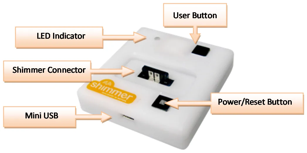
Figure 1‑1 Shimmer Dock – enclosure view
The different features of the Dock are summarised in Table 1‑1.
| Item | Shimmer3 |
|---|---|
| Power/Reset Button | Reset (quick press) |
| Power/Reset Button Indicator | Solid Green when Shimmer is powered on |
| User Button | Application specific signal to Shimmer |
| Charge Indicator | Solid Yellow during primary charging state |
| MicroSD Indicator | Blinks Blue with host PC access to Shimmer microSD |
| UART Indicator | Blinks Orange during programming (BSL) or UART activity |
The Dock connects to a PC via a USB cable. The microSD card access needs no driver. Programming and configuring the Shimmer use the Dock’s FTDI USB serial converters, whose driver Windows normally installs itself when the Dock is first connected. Check that it is version 2.12.0.0 or later, as described below.
1.1. USB Serial Converter Driver Installation
Checking the driver, and installing it by hand if needed, are described in Installing in the Consensys User Guide: Checking the drivers and Installing the FTDI driver by hand. The Dock adds two USB Serial Converter entries (A and B) and two USB Serial Port entries; the port with the lower number is the Programming Port.
1.2. Placing a Shimmer in the Shimmer Dock
The Dock connects to the Shimmer via the External Connector. The External Connector is keyed and does not require force to insert. Insert the Shimmer with the Bluetooth ID label facing away from the USB cable.
Warning: Forcing the connector may cause permanent damage to your Shimmer.
When the Shimmer is placed in the Dock, the green LED on the Power/Reset button on the dock will light up green if the Shimmer is powered on. If it does not light up then one of the following may have occurred:
Shimmer unit may be powered off.
Shimmer unit may not be inserted properly.
The Dock may not be powered via the USB cable.
Ensure that the Shimmer unit is inserted properly and that the programming dock is powered via the USB cable. For Shimmer3, use the slide-switch on the side of the device to ensure that it is powered on.
1.3. Charging the Shimmer
In order to use the Dock as a charging device, simply connect the USB cable of the Dock to a powered USB socket and insert the Shimmer unit into the Dock.
Note: You should make sure your Dock is powered when a Shimmer is docked as the Shimmer battery will discharge if it is left idle in a Dock that is not powered.
The state of the charge indicator LED is an indication of charge phase for the battery. There are three phases to Shimmer battery charging, illustrated in Figure 1‑2. The background colour on the graph in Figure 1‑2 indicates the colour of the charge indicator LED on the Dock during each phase.
Phase 1 is a Preconditioning Phase and is only required when the battery voltage has dropped below a minimum threshold. The battery voltage should not drop below this minimum threshold with normal everyday use however if a Shimmer is left idle for a long period of time the battery may self-discharge to a voltage below the minimum threshold. During the Preconditioning Phase a low current (12.5mA) is applied to bring the voltage to the Minimum Charge Voltage. The length of pre-conditioning will depend on the extent to which battery is discharged. For example a Shimmer that has been unused for months and was stored discharged may have a lengthy pre-conditioning phase. For the most efficient recharging after a deep discharge, it is recommended to program the Shimmer unit with the Sleep firmware image. During the Preconditioning Phase the charge indicator LED on the Dock will be off.
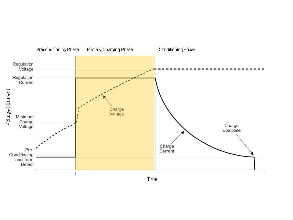
Figure 1‑2 Shimmer Battery Charging Phases. The background colour on the graph indicates the colour of the charge indicator LED on the Dock during this phase.
Phase 2 is the Primary Charging Phase. This phase is the standard charging phase and involves the application of a constant current (125mA) to bring the battery voltage to the Regulation Voltage level. During this phase the charge indicator LED on the Dock will illuminate yellow.
Phase 3 is the Conditioning Phase. The charger will continue to condition the battery while the Shimmer remains inserted in the charger. For maximum operating life allow as much conditioning time as your needs allow. During this Phase the charge indicator LED on the Dock will mostly be off. Depending on the firmware image that is programmed on the device, the charge indicator LED may intermittently light up. This is because a heavy load may momentarily bring the battery voltage below the threshold for the Conditioning Phase, causing the Primary Charging Phase to be re-entered.
The standard Shimmer battery is 3.7 V, 400 mAh on Shimmer3R and current Shimmer3 units and 450 mAh on earlier Shimmer3 units. Charge times, and the charger’s limits for larger batteries, are in Charging the Shimmer in the Shimmer3/3R User Manual.
1.4. microSD Card Access
When a Shimmer with microSD card is inserted into a Dock that is connected to a PC, the standard drivers on the host system should mount the microSD card as though it were a USB flash key. Depending on the specifics of your system, a few things may happen:
A window may open to display the contents of the Shimmer’s flash
A prompt window may pop-up and ask you what you want to do
Nothing may happen, but when you click on the drive letter or volume name associated with the USB port of the USB Dock, the contents of the Shimmer flash may be browsed.
There are a few requirements for this interaction to work:
The Shimmer must be powered.
Your SD card must have a compatible format: a FAT file system (Shimmer3R also accepts exFAT; see Choosing a microSD card in the Shimmer3/3R User Manual). If this isn’t the case, you may be prompted to reformat the card. Be careful – irreversible data loss will occur! Otherwise a binary/raw disk utility (such as DD) must be used to copy or access data.
Some Shimmer applications may block this ability or limit mounting to specific times during operation due to legacy compatibility issues, or pending disk operations on Shimmer. This will result in a blinking blue LED on the Dock followed by a time-out from the HOST, or a blue LED on the Dock that turns off (media is detected but fails OS poll). You can try to re-insert the Shimmer, inspect the code, or contact the developer.
1.5. Programming the Shimmer 3
Consensys programs a Shimmer in the Dock: see Programming Firmware in the Consensys User Guide. The Dock’s orange UART indicator blinks while it programs.
Shimmer3R: Consensys updates Shimmer3R firmware in the Dock, in a Consensys Base, or over the Shimmer3R’s USB-C cable. (The purple flash on its lower LED shows only while the user button is held at power-on, before the Shimmer3R enters its bootloader.) See Programming a Shimmer in the Shimmer3/3R User Manual.
2. Legacy
2.1. Compatibility
The previous version of the Shimmer Dock (v2.1) can be identified by the two LED indicators – one for MicroSD/UART activity and the other for charge indication, as shown in Figure 2‑1. It should be noted that this version of the Dock is not fully compatible with Shimmer3. The charge indicator will not light for Shimmer3 and SD card access through the dock will not work on some PCs.
MicroSD Indicator/ UART Indicator
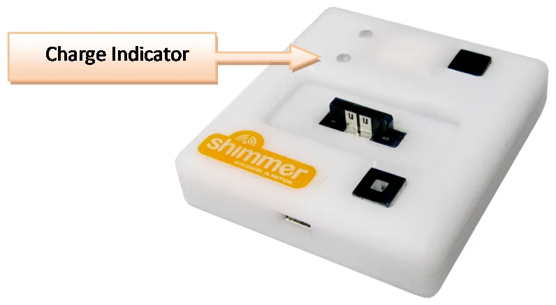
Figure 2‑1 Shimmer Programming Dock v2.1
3. Troubleshooting
USB UART drives fail to load
Occasionally the USB UART drivers will fail to load. This condition typically happens when the Dock has been unplugged and is often indicated by a solid UART activity LED. The simple fix is to unplug the USB cable and retry. If this process fails to remedy the situation, please contact Shimmer Research support for assistance.
PC fails to recognise the SD card
I have inserted an SD card into my Shimmer unit but the PC fails to recognise it when I view the list of Devices with Removable Storage as in Figure 3‑1.
Try one or more of the suggested options below to attempt to resolve the problem.
Make sure that the Shimmer Dock drivers installed correctly.
Power off and power on your Shimmer unit.
Unplug and re-plug the Shimmer Dock.
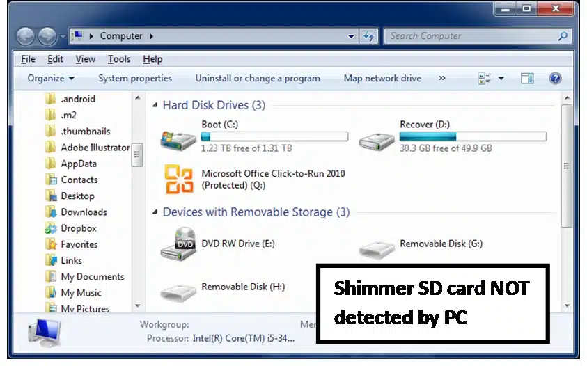
Figure 3‑1 Shimmer SD Card NOT detected by PC
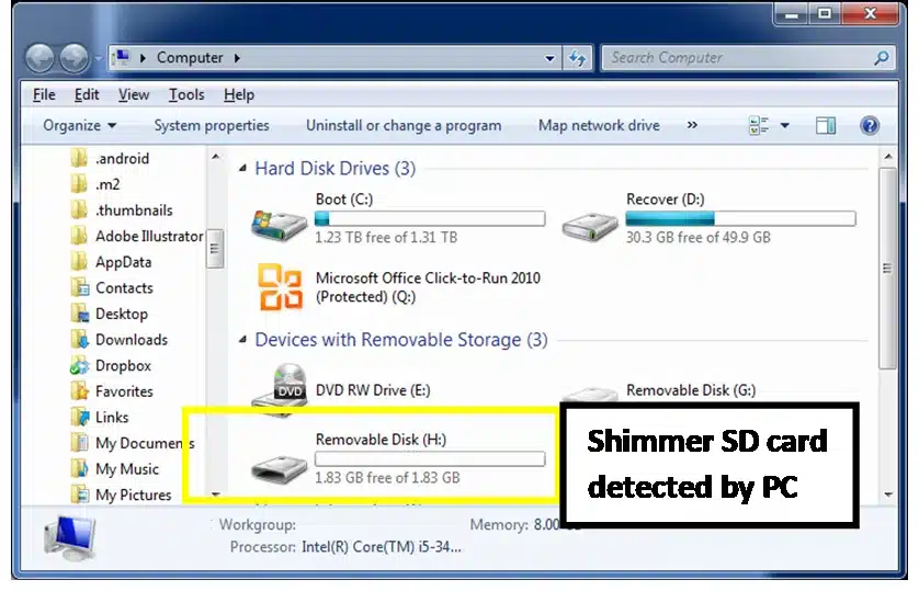
Figure 3‑2 Shimmer SD Card detected by PC
The FW did not program correctly
Make sure the Shimmer is switched on (green LED in Reset Button is on).
Make sure the USB cable is fully inserted in the Dock as depicted in Figure 3‑3 USB cable inserted.
Try again. If programming fails after a few attempts, contact us through our contact page
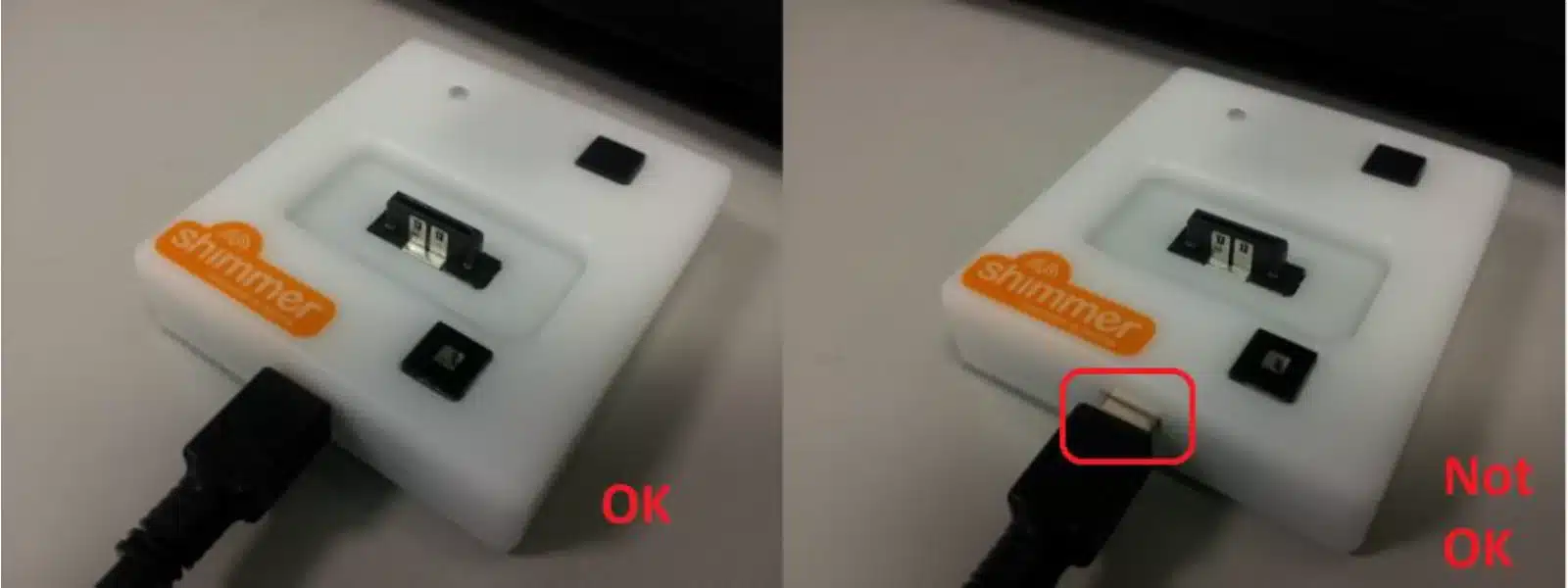
Figure 3‑3 USB cable inserted
Legal notices
Legal Notices and Disclaimer
Redistribution IS permitted provided that the following conditions are met:
Redistributions must retain the copyright notice, and the following disclaimer. Redistributions in electronic form must reproduce the above copyright notice, this list of conditions and the following disclaimer in the documentation and/or other materials provided with the document.
Neither the name of Shimmer Research Ltd. nor the names of its contributors may be used to endorse or promote products derived from this document without specific prior written permission.
THIS DOCUMENT IS PROVIDED BY THE COPYRIGHT HOLDERS AND CONTRIBUTORS “AS IS” AND ANY EXPRESS OR IMPLIED WARRANTIES, INCLUDING, BUT NOT LIMITED TO, THE IMPLIED WARRANTIES OF MERCHANTABILITY AND FITNESS FOR A PARTICULAR PURPOSE ARE DISCLAIMED. IN NO EVENT SHALL THE COPYRIGHT OWNER OR CONTRIBUTORS BE LIABLE FOR ANY DIRECT, INDIRECT, INCIDENTAL, SPECIAL, EXEMPLARY, OR CONSEQUENTIAL DAMAGES (INCLUDING, BUT NOT LIMITED TO, PROCUREMENT OF SUBSTITUTE GOODS OR SERVICES; LOSS OF USE, DATA, OR PROFITS; OR BUSINESS INTERRUPTION) HOWEVER CAUSED AND ON ANY THEORY OF LIABILITY, WHETHER IN CONTRACT, STRICT LIABILITY, OR TORT (INCLUDING NEGLIGENCE OR OTHERWISE) ARISING IN ANY WAY OUT OF THE USE OF THIS DOCUMENT, EVEN IF ADVISED OF THE POSSIBILITY OF SUCH DAMAGE.
