
1. Introduction
Shimmer is a small wireless sensor platform well suited for wearable applications. The integrated kinematic sensors, large storage and low-power standards based communication capabilities enable emerging applications in motion capture, long-term data acquisition and real-time monitoring.
Shimmer3, the latest revision of the Shimmer platform includes improvements to the original design based on years of field trials and deployments. We have made improvements in wearability while expanding capabilities with a flexible kinematic sensor array, more powerful CPU and improved user interface. The terms ‘Shimmer’ and ‘Shimmer3’ are used interchangeably in this manual, to refer to the Shimmer3 device. Much of the information applies generically to Shimmer Products.
This manual covers both Shimmer3 and Shimmer3R. Shimmer3R is the current generation of the Shimmer3 platform. It works with the same software, runs the same LogAndStream firmware behaviour and is configured in the same way. Where Shimmer3R differs, the text says so in a Shimmer3R: note, and Shimmer3R hardware describes its hardware in full. Text without a note applies to both.
To tell which you have, look at the label on the Shimmer, which names the product. Its Bluetooth device name also tells them apart: a Shimmer3R appears as two devices, Shimmer3R-XXXX-BT and Shimmer3R-XXXX-BLE, and a Shimmer3 as Shimmer3-XXXX (a Shimmer3 with the dual-mode RN4678 radio also shows a second, Bluetooth Low Energy entry). Consensys also shows the hardware version of a connected device.
If you are new to the Shimmer platform, there is Quickstart information in Section 2, whilst Section 3 gives a high level overview of the Shimmer platform. Section 2 (Quickstart) is essential reading, Section 3 (Shimmer Platform Overview) is recommended reading and the remaining sections are best browsed based on personal interest and development goals. For details on legacy devices please refer to Legacy Support.
2. Quickstart
This Quickstart covers what every Shimmer user needs first: switching on, the LEDs, charging, pairing and a first data stream. The Consensys User Guide takes you through configuring, logging and streaming in Consensys step by step.
Shimmer units are shipped pre-programmed with the LogAndStream firmware program which allows for Shimmer configuration and data capture over Bluetooth as well as capturing data onto the SD card of the Shimmer. This Quickstart guide assumes the device has been programmed with LogAndStream v0.8.0 or later.
2.1. Powering On/Off the Shimmer
Use the slide switch to turn the Shimmer On/Off, as shown in Figure 2‑1. Some applications may use the user push-button to switch between suspend and active modes; details of this functionality can be found in the appropriate application manual.
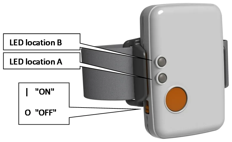
Figure 2‑1 Shimmer3 in enclosure
2.2. LED indication
The Shimmer has two LED locations (Figure 2‑1). The upper LED (location B) shows what the Shimmer is doing; the lower LED (location A) shows its health: the button, errors, the battery and charging. On Shimmer3 the lower location holds green, yellow and red LEDs, and the upper location green and blue.
Shimmer3R: Shimmer3R has one RGB LED in each location instead of five single-colour LEDs. It shows the same patterns, with the colour made by the one LED: yellow is red and green together, and “green and blue together” is a single cyan LED. Where the two generations differ, the tables say so.
The patterns run at three speeds. Fast is five flashes a second (0.1 s on, 0.1 s off). Slow is 1 s on and 1 s off. A blip is a single 0.1 s flash, every 2 s on the upper LED and every 5 s for the battery on the lower LED. The LEDs keep time with the Shimmer’s clock, so Shimmers whose clocks were set together flash together.
2.2.1. Upper LED: Bluetooth enabled
These patterns apply when Bluetooth is enabled in the configuration and SD-sync mode is off, which is the usual set-up. They are listed in priority order: when two apply, the one higher in the table shows.
| LED | What you see | What it means |
|---|---|---|
| Shimmer3 Shimmer3R | Green and blue together (Shimmer3R: cyan), flashing fast | The clock is not set (Real-time clock). Not shown while the Shimmer is logging or streaming |
| Green, flashing (0.2 s on, 0.2 s off) | Configuring | |
| Blue, slow (1 s on, 1 s off) | Streaming | |
| Green, slow (1 s on, 1 s off) | Logging, with no Bluetooth connection | |
| Blue for 2 s, then green for 1 s, repeating | Logging, with a Bluetooth connection | |
| Green 1 s, off 1 s, blue 1 s, off 1 s, repeating | Logging and streaming | |
| Blue, solid | Connected over Bluetooth, not logging or streaming | |
| Blue, flashing fast (Shimmer3 with an RN4678 radio only) | A Bluetooth link is up but no application has opened the connection yet | |
| Blue blip every 2 s | Waiting for a Bluetooth connection | |
| Nothing | The Bluetooth radio is off, and the Shimmer is not logging or streaming |
Table 2‑1 Upper LED patterns with Bluetooth enabled
2.2.2. Upper LED: Bluetooth disabled, or SD-sync mode
When Bluetooth is disabled in the configuration, or the Shimmer is in SD-sync mode (Synchronised logging), the upper LED uses these patterns instead. The clock-not-set and configuring patterns of 2.2.1 still take priority.
| LED | What you see | What it means |
|---|---|---|
| Green, slow (1 s on, 1 s off) | Logging | |
| Green blip every 2 s | Not logging | |
| Blue double flash every 2 s, beside the green | SD-sync mode: Bluetooth is on and the Shimmer is not connected | |
| Blue, flashing fast, green hidden | SD-sync mode: connected, to a host or to another Shimmer for a sync exchange. While logging, each sync exchange shows as a burst of fast blue | |
| Green for 1 s, then blue for 1 s, repeating | SD-sync mode: a node that is logging but has not yet received its first sync. It stops once the first sync arrives |
Table 2‑2 Upper LED patterns with Bluetooth disabled or in SD-sync mode
With Bluetooth disabled the Shimmer never shows blue. Green 1 s on and 1 s off looks the same as “logging, with no Bluetooth connection” in 2.2.1: both mean the Shimmer is logging.
2.2.3. Lower LED
Listed in priority order. “On USB” applies to Shimmer3R, which charges from its USB-C port as well as in a dock.
| LED | What you see | What it means |
|---|---|---|
| Green, solid | The user button is held | |
| Red, solid, not docked | Host software has turned the LED on with its Toggle LED command. It stays on, hiding the battery display, until the host sends the command again or the Shimmer is reset. Docked, it looks the same as charging | |
| Green, flashing fast, not docked | SD card missing, or a file on it cannot be written. Can be switched off in the configuration (Experiment settings, SD Error). A Shimmer3R on USB but not docked shows this instead of its charging colour | |
| Red, flashing fast, docked or on USB | Bad battery, or a charger error | |
| Red, solid, docked or on USB | Charging | |
| Green, solid, docked or on USB | Fully charged | |
| Yellow, solid, docked or on USB | Charging suspended | |
| Nothing, docked or on USB | Charging state not known yet. This shows for a moment after the Shimmer is docked or plugged in, until it next reads its battery | |
| Green, yellow or red blip every 5 s, not docked | Battery high, medium or low (Battery level on the LED) |
Table 2‑3 Lower LED patterns
The battery blip lasts a tenth of a second in every five, so watch for at least six seconds before deciding a Shimmer shows nothing.
2.2.4. At power-on
| LED | What you see | What it means |
|---|---|---|
| Lower LED: green, yellow, red, yellow, green …, one step every half second; upper LED off | Booting normally. The sweep runs until the Shimmer has finished starting up | |
| Lower LED (Shimmer3R only): purple, flashing (0.2 s on, 0.2 s off) | The user button is held at power-on. Keep holding it for 3 seconds and the Shimmer3R enters its bootloader; release it sooner and it starts normally | |
| Shimmer3 Shimmer3R | Lower LED: red, flashing fast (Shimmer3); yellow and red alternating, with no off phase (Shimmer3R) | Starting the sensors is taking longer than it should (over 1 s). On Shimmer3R this step also hands over the SD card, so a slow card can cause it. If the pattern continues, power-cycle the Shimmer; if it repeats, contact us |
| Lower LED: green, flashing fast | Loading the configuration is taking longer than it should (over 2 s). This step reads the SD card, so a slow or faulty card is a common cause | |
| Lower LED (Shimmer3 only): yellow, flashing fast | The Bluetooth radio did not respond. It appears after about a minute of retries and stays until the Shimmer is reset. Power it off, dock it for a minute and power it on; if it repeats, contact us |
Table 2‑4 LED patterns at power-on
The two slow-start patterns stop, and the Shimmer carries on starting up, if the slow step finishes.
The LED feedback reference in the firmware repository explains how the firmware chooses each pattern, for developers.
2.3. Charging the Shimmer
Charge a Shimmer in a Shimmer Dock, a Consensys Base or a Multi Charger, each connected to power. Insert it with the Bluetooth ID label facing away from the USB cable.
Warning: The connector is keyed. Forcing it may damage your Shimmer; if it does not go in easily, check the orientation.
While a powered-on Shimmer charges (docked, or on USB-C for a Shimmer3R), its lower LED is red; when the battery is full it turns green. Steady yellow means charging is suspended, and fast-flashing red means a bad battery or a charger error. The Dock and the Base have their own charge LEDs, which follow the charger rather than the Shimmer’s firmware: see the Shimmer Dock User Guide. Every lower-LED pattern is in Lower LED. A Shimmer that is switched off still charges, but its LEDs stay dark.
Note: Shimmer3 firmware older than LogAndStream v1.00.003 does not show the charging state. Its lower LED shows the battery level instead, docked or not: green, yellow or red, so a charging Shimmer can show yellow or green. Every Shimmer3R release shows the charging state.
A standard battery charges fully in about 4.5 hours. The charger charges at 125 mA and stops after 6.16 hours, which limits it to about 770 mAh; to restart the timer, undock the Shimmer for about 15 seconds. A Shimmer left in a Dock that is not powered slowly discharges. For batteries of other sizes, see Battery Replacement.
2.4. Pairing a Shimmer
Before a Shimmer can stream over Bluetooth, it must be paired with the computer, phone or tablet that receives the data. Each Shimmer needs pairing only once.
Note: The host side machine must have a plug-in or built-in Bluetooth radio installed and activated to continue.
Shimmer3R: A Shimmer3R supports both Classic Bluetooth and Bluetooth Low Energy. With both enabled in its configuration, it appears in the Windows device list twice: Shimmer3R-XXXX-BT (Classic) and Shimmer3R-XXXX-BLE, where XXXX is taken from its Bluetooth address. Pair Shimmer3R-XXXX-BT to get the COM port the steps below use. The BLE entry is for applications that connect over Bluetooth Low Energy, and gives no COM port. No PIN is needed for either. A Shimmer3R in SD-sync mode uses the PIN 1234, as Shimmer3 does.
2.4.1. Bluetooth Pairing in Windows
Pair each Shimmer in Windows Bluetooth settings, with the Shimmer switched on and within about 10 m; Pairing in the Consensys User Guide shows the steps. Pair the Bluetooth Classic entry, which is the one that gives a COM port. A Shimmer3 is listed as Shimmer3-XXXX (or RN42-XXXX on early units), where XXXX is the end of its Bluetooth address, printed on its label, and asks for the PIN 1234. A Shimmer3 with the RN4678 radio is also listed a second time, as S3BLE-XXXX: that is its Bluetooth Low Energy entry, which gives no COM port. A Shimmer3R’s two entries are described in the note above.
Windows shows a paired Shimmer as Disconnected until an application connects to it; that is normal.
Finding the COM port: Consensys finds paired Shimmers itself, but many other applications, including the MATLAB and LabVIEW drivers, need the COM port Windows has assigned to the Shimmer. Open Control Panel → Hardware and Sound → Devices and Printers, right-click the Shimmer, select Properties and go to the Services tab. The COM port is the Serial Port (SPP) service (COM74 in Figure 2‑2).
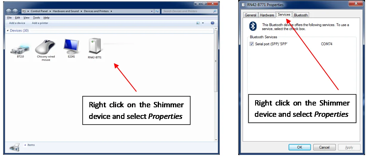
Figure 2‑2 Locating the COM port associated with the Shimmer
2.4.2. Other operating systems
Consensys runs on Windows. On Linux and macOS, pair the Shimmer with the system’s Bluetooth tools (for example bluetoothctl on Linux) and connect from your own software; the Python library pyshimmer works there. To stream to a phone or tablet, see Setting up a Shimmer data stream.
2.5. Setting up a Shimmer data stream
A Shimmer streams its data live over Bluetooth, to a PC, a phone or tablet, or your own software. It needs LogAndStream firmware, which every Shimmer is shipped with. Choose by where you want the data:
| To stream to | Use | How |
|---|---|---|
| A Windows PC | Consensys. ConsensysBASIC streams from one Shimmer, ConsensysPRO from several, and either can record the stream and add event markers. | Open LIVE DATA, connect to the Shimmer, configure it, then start streaming. The Consensys User Guide describes each step. |
| An Android phone or tablet | ShimmerCapture, on Google Play. It works with Shimmer3 and Shimmer3R, streams from one Shimmer, graphs the data and can save it to a file: a quick way to see a Shimmer’s data without a PC. | Install it from Google Play, pair the Shimmer with the phone or tablet, then connect, choose the sensors and start streaming from the app’s menu. |
| Your own software | The Shimmer APIs and instrument drivers, for Java, Android, C#, MATLAB and LabVIEW, and the third-party pyshimmer for Python. | See Software Development. |
Table 2‑5 Ways to stream data
While a Shimmer streams, its upper LED flashes blue, 1 s on and 1 s off (LED indicators).
3. Shimmer3 Platform Overview
This section provides an overview of the main components of the Shimmer3 platform. The scope and level of detail provided here is aimed at the general Shimmer user and should be sufficient for understanding the core concepts of the Shimmer3 platform. For more specific and detailed information, please refer to the later sections of this document along with the additional user guides, which are referred to throughout the document.
3.1. Components
Table 3‑1 lists the key components of the Shimmer3 platform.
Feature |
Purpose |
Component/Capabilities |
I/O |
Capture of sensor and user data. |
Integrated
|
Processing |
Control operating state. Provide best signal quality. Operational alerts and messages. |
MSP430F5437A CPU
|
Storage |
No loss of data while mobile, during network outages or while changing batteries. |
microSD slot
|
Communication |
Hi-reliability. Standards-Based . Mobility. |
Class 2 Bluetooth Radio
|
Power |
Long operating life. Safe operation. |
|
Table 3‑1R lists the same for Shimmer3R.
| Feature | Shimmer3R |
|---|---|
| I/O – integrated | 3-axis low-noise accelerometer and 3-axis gyroscope (ST LSM6DSV) 3-axis wide-range accelerometer (ST LIS2DW12) 3-axis magnetometer (ST LIS2MDL) 3-axis ±200 g high-g accelerometer (Analog Devices ADXL371), Shimmer3R IMU only Pressure and temperature sensor (Bosch BMP390, or BMP581 on later units) 2 RGB status LEDs Software-defined user button |
| I/O – expansion | 7 analogue expansion channels (Ext A0–A2, Int A0–A3), read by an external TI ADS7028 12-bit ADC with a 3.0 V reference 18-position rugged external connector (Hirose ST60-18P(30); mates with the ST40X-18S), the same as Shimmer3’s: charging, Dock and Base connection, SD card access, external analogue channels and tethered sensor extensions USB-C socket on the side of the unit No internal expansion connector |
| Processing | ST STM32U5A5 (32-bit Arm Cortex-M33) 2.5 MB RAM, 4 MB flash Runs at 48 MHz 32.768 kHz crystal for the real-time clock and sample timing; the clock is kept across a reset |
| Storage | microSD slot microSDHC and microSDXC cards (FAT32 or exFAT) Read by a PC through the Shimmer Dock or Consensys Base, or over USB-C as a removable drive Files can be listed, read and deleted over Bluetooth |
| Communication | Bluetooth Classic and Bluetooth Low Energy Ezurio Vela IF820 module (453-00171C), integrated chip antenna USB-C: serial port for configuration and firmware update, and the SD card as a removable drive (data is not streamed over USB) |
| Power | 3.7 V, 400 mAh rechargeable lithium battery Battery voltage monitoring Smart charger Soft power control of the Bluetooth radio and sensor supplies |
Table 3‑1R Shimmer3R Mainboard Key Features
Figure 3‑1 shows the individual components of the Shimmer3. To open the case, loosen the two screws with a T-6 Torx screwdriver and open the case carefully by pulling up on the screw side and carefully disengaging the tabs on the opposite side of the unit. Note the position of the PCB, wires, button, slide-switch actuator (if present), and battery for re-assembly. For more detailed instructions on assembly and disassembly, refer to Appendix C – Opening or assembling the Shimmer3 enclosure.
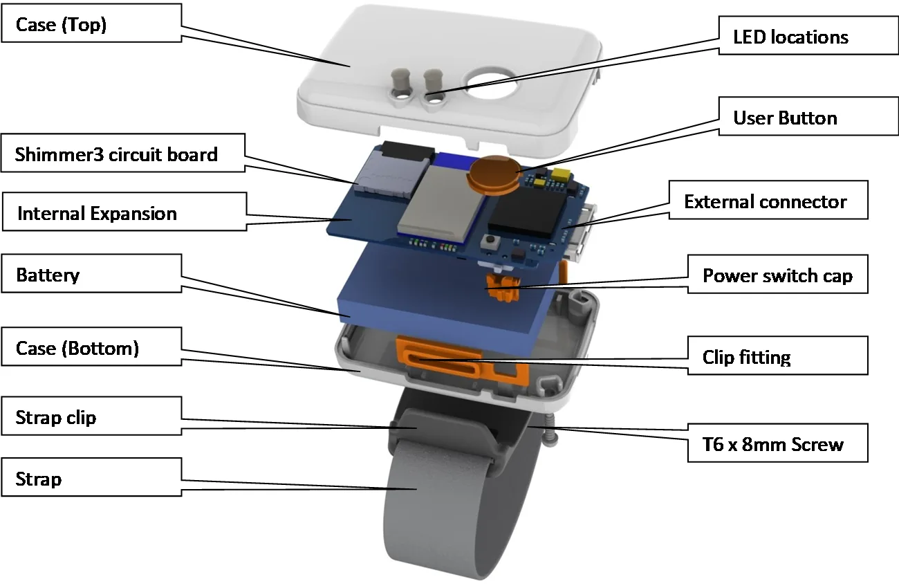
Figure 3‑1 Shimmer3 Exploded view
3.1.1. Power switch
Shimmer units arrive from the factory programmed with LogAndStream firmware with power switched off. To power-on, use the slide switch (highlighted in Figure 3‑1).
The power-off feature on the Shimmer unit is intended for storage or transportation. If you wish to leave a Shimmer in a low-power state without turning off the device, you should program the Shimmer with the Sleep firmware (see Section 5).
3.1.2. Battery
A Shimmer runs from a rechargeable 3.7 V lithium battery: 400 mAh on Shimmer3R and current Shimmer3 units, 450 mAh on earlier Shimmer3 units. The battery, on Shimmer3 and Shimmer3R, contains a safety circuit board with over-current protection, which can trigger if a component short is created by a faulty peripheral or if components are bridged while the enclosure is open. The battery will return to normal operating condition after the short is removed and the unit is placed back in a Dock.
The Shimmer operating life when using these batteries depends on a number of factors including which, if any, radio is in use, which sensors are enabled and the rate at which data is being sampled and transferred. Battery life estimation information for a number of different configurations is provided in section 6.2.3 with the battery’s voltage levels and how to estimate its remaining capacity.
The lower LED shows the battery level, and the Shimmer can stop a recording before the battery runs flat: see Battery level on the LED and Low-battery auto-stop. There is also hardware low-battery protection, which prevents damage to the battery or the Shimmer. If a recording fails to start, or stops abruptly once streaming or logging starts, the battery may need charging. For details on battery re-charging please refer to Charging the Shimmer. If you suspect a fault with the battery, see the Troubleshooting and FAQs.
3.1.3. User button
There is an orange-coloured user button on the Shimmer3 (highlighted in Figure 3‑1), whose function is defined by firmware. Users should note that this button does not provide tactile feedback. All firmware solutions provided by Shimmer include visual feedback when the user button is pressed and it is recommended that any users who wish to develop firmware do the same.
Shimmer3R: Consensys starts the Shimmer3R’s bootloader itself when it updates the firmware, so you need not. To start it by hand, for example to recover a Shimmer3R whose firmware no longer runs, hold the user button while switching it on. The lower LED flashes purple while you hold the button; keep holding for about 3 seconds, until the flashing stops. The Shimmer3R is then in its bootloader, ready for Consensys to update it. If you release the button sooner, it starts normally. The bootloader does not time out: to leave it without updating, switch the Shimmer3R off and on again.
3.1.4. Shimmer LED Indicators
Two LED locations (highlighted in Figure 3‑1) show the Shimmer’s state. The lower indicator is tri-coloured (green, yellow and red) and shows its health; the upper indicator is bi-coloured (blue and green) and shows what it is doing. What each pattern means is in LED indication.
Shimmer3R: Each indicator is a single RGB LED, so it can show any of these colours, and also cyan and purple.
3.1.5. MicroSD Card Socket
The Shimmer mainboard contains a microSD card socket to incorporate extra memory resources, with capacities up to 32GB. This allows the additional storage of data while the Shimmer is not streaming and ensures no loss of this data while mobile, during network outages or while changing batteries.
You will find the microSD card socket on the corner of the PCB with a label printed on the PCB in the socket opening. As Shimmer has a power switch on this component, there is no drawback to leaving a card installed at all times. The card socket is spring-loaded and you can insert the card from the side without complete disassembly.
The microSD card may be accessed using the Shimmer Dock or Consensys Base. For more information on microSD card access please refer to the Shimmer Dock User Guide.
For further hardware-based information on the microSD card socket, please refer to Section 6.2.2 of this manual. For information on firmware solutions for using the microSD card please refer to Section 5 of this manual.
Note: Shimmer3 supports microSD and microSDHC cards up to 32 GB, but not microSDXC cards. Shimmer supplies an 8 GB SanDisk card. For choosing another card, see Choosing a microSD card.
Shimmer3R: Shimmer3R firmware can also list, read and delete the files on its card over Bluetooth, without docking (Bluetooth streaming). Consensys does not use this yet.
3.1.6. Internal Connector
The expansion connector is on the top side of the Shimmer and consists of both J6 and J7, as shown in Figure 3‑2. It is used to connect to internal daughter boards. All expansions will include appropriate enclosures.
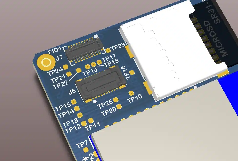
Figure 3‑2 Shimmer3 mainboard’s internal expansion connector
Care should be taken when making decisions about hardware configuration, in order to minimise the number of times that boards are removed from and inserted into the internal connector. The connector is rated for up to four insertions.1
Never force the expansion board when connecting it to the Shimmer mainboard and be sure to install it with the board aligned with dimensions of the Shimmer PCB. The connection is keyed and its orientation is visually obvious. The expansion enclosure may be self-aligning to assist in the assembly process.
For the connector’s pin assignment, see the Shimmer3/3R Hardware Developer Reference.
Shimmer3R: Shimmer3R has no internal connector, so internal expansion boards such as the PROTO3 Mini cannot be fitted to it.
3.1.7. External Connector
The Shimmer mainboard connects to the Shimmer Dock and Shimmer Multi Charger via the External Connector (highlighted in Figure 2‑1). The External Connector can also be used to attach external expansion boards. The External Connector is keyed and does not require force to attach to a device.
For the connector’s pin assignment, see the Shimmer3/3R Hardware Developer Reference.
Shimmer3R: Shimmer3R also has a USB connection. On a PC it appears as a serial port, which Consensys uses for configuration and firmware update, and as a removable drive holding the SD card. Data cannot be streamed over USB; use Bluetooth. While the Shimmer3R is connected to USB, or docked, it does not log to its SD card, because the card is handed to the PC.
The USB-C socket is on the side of the Shimmer3R. Its external connector is the same as the Shimmer3’s, so it fits the same Dock, Consensys Base and Multi Charger.
3.2. Shimmer Dock
The Shimmer Dock holds one Shimmer and connects it to a PC over USB. It charges the Shimmer, gives the PC access to its microSD card as a USB drive, and lets Consensys configure and program it. The current dock is the Shimmer Programming Dock v3: a square white enclosure with a power/reset button, a black user button and indicator LEDs.
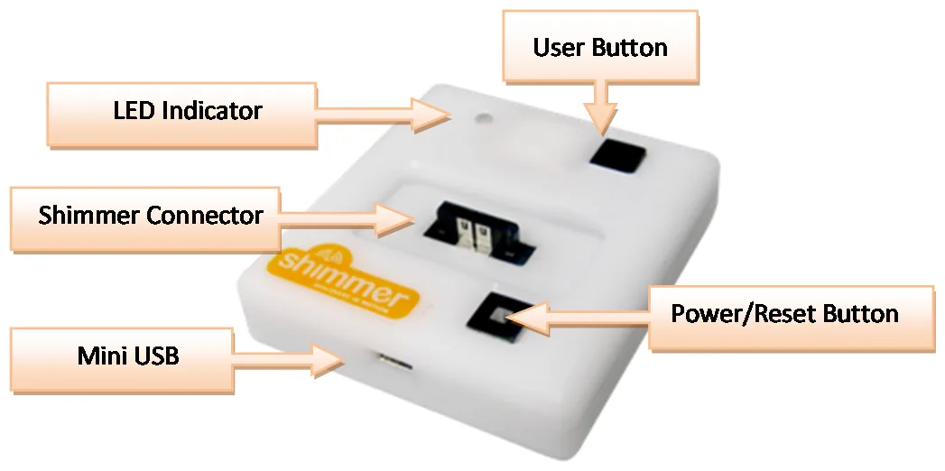
Figure 3‑3 Shimmer Dock – enclosure view
Insert the Shimmer with its Bluetooth ID label facing away from the USB cable. The connector is keyed; never force it. Keep the Dock powered while a Shimmer sits in it: a Shimmer in an unpowered Dock slowly discharges.
Shimmer3R: Shimmer3R works in the Shimmer Dock as Shimmer3 does: charging, SD card access, configuration and firmware update. It can also connect to the PC directly with a USB-C cable (External Connector).
The Shimmer Dock User Guide describes the Dock’s buttons and LEDs, its USB drivers, charging, microSD card access and troubleshooting.
3.3. Consensys Base
Consensys Base hardware (referred to as the Base in this section) is a multi sensor management system with an integrated software solution (see the Consensys User Guide), for the simple and effective management of all your Shimmer data. The Base allows users to easily configure and capture data from up to 15 Shimmers simultaneously and provides ability to:
- Charge Shimmers
Data download through MicroSD Card access
Program Shimmers
Configure Shimmers
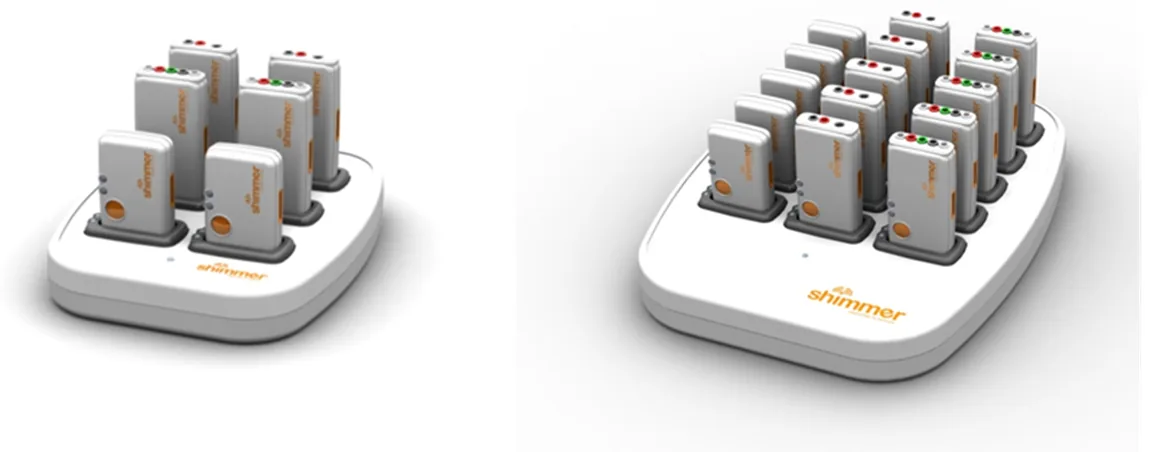
Figure 3‑4 Consensys Base (Base6U and Base15U from L-R)
Shimmer3R: Shimmer3R works in the Consensys Base6 and Base15 as Shimmer3 does: charging, SD card access, configuration and firmware update.
3.3.1. Consensys power-up order
1. Undock all Shimmers from the Base.
2. Plug in the mains power supply and connect to the Base.
3. Connect the USB cable from a computer to the Base.
4. Wait for all drivers to install.
5. Dock Shimmers.
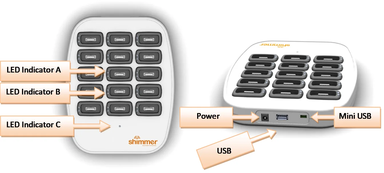
| Item | Status / Function |
|---|---|
| LED Indicator A | Solid Green if a Shimmer is docked |
| LED Indicator B | Active slot indicator**; Solid Blue** if SD access**, Solid Orange** if UART access |
| LED Indicator C | Blinks Orange if Base is powered and Consensys software is running |
| Power | 12V, 5A power supply |
| USB | USB hub for chained Consensys Bases |
| Mini USB | For UART communications with the Shimmers in the Base |
Table 3‑2 Consensys Base features
3.4. Other Accessories and Shimmer Platform Components
3.4.1. Shimmer3 Variations
Besides the standard Shimmer3 IMU, Shimmer makes sensing units and expansion boards for other signals. Each has its own user guide, with its specifications and how to use it:
- IMU: the accelerometers, gyroscope and magnetometer every Shimmer carries, and calibrating them.
- ECG and EMG: digital front ends for ECG, respiration and EMG.
- GSR+: skin conductance, with a 3.5 mm jack for an external sensor such as the Optical Pulse Sensor.
- Bridge Amplifier+: load cells, strain gauges and resistance measurement.
- PROTO3 Series: prototyping boards for connecting your own sensors.
- External Expansion Board: access to the external connector’s signals.
Shimmer3R is made in several board revisions, written as a board number, a major revision and a minor revision (for example SR31-11-2). Each product has a production base revision, and its minor revisions -1, -2 and -3 are the same board with parts changed. Table 3‑3 lists them.
| Product | Production base | -1 |
-2 |
-3 |
|---|---|---|---|---|
| Shimmer3R IMU (SR31) | SR31-11-0 | SR31-11-1 | SR31-11-2 | SR31-11-3 |
| Shimmer3R Proto3 Deluxe (SR38) | SR38-4-0 | SR38-4-1 | SR38-4-2 | SR38-4-3 |
| Shimmer3R ExG (SR47) | SR47-8-0 | SR47-8-1 | SR47-8-2 | SR47-8-3 |
| Shimmer3R GSR+ (SR48) | SR48-8-0 | SR48-8-1 | SR48-8-2 | SR48-8-3 |
| Shimmer3R Bridge Amplifier (SR49) | SR49-4-0 | SR49-4-1 | SR49-4-2 | SR49-4-3 |
Table 3‑3 Shimmer3R variants
What each revision changes for a user:
- Production base (-0): Bosch BMP390 pressure sensor, and the ADXL371 high-g accelerometer fitted on every product.
- -1: the ADXL371 is fitted only on the IMU (SR31-11-1).
- -2 and -3: as -1, with the Bosch BMP581 pressure sensor in place of the BMP390.
The other part changes between revisions do not change what a Shimmer3R measures or how it is used. The board revisions reference in log-and-stream-common lists every revision and its parts.
3.4.2. Multi Charger
The primary function of the Multi Charger (see Figure 3‑5) is to allow for the simultaneous charging of up to six Shimmers. The Multi Charger also has a Reset Button which allows for synchronised reset of multiple Shimmers.
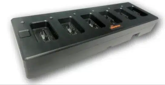
Figure 3‑5 Shimmer Multi Charger
The Multi Charger is a legacy device, and has no separate guide; charge Shimmers in it, Shimmer3 or Shimmer3R, as described in Charging the Shimmer.
3.4.3. Shimmer3 JTAG Developer Board
The Shimmer3 JTAG Developer Board sits between a Shimmer3 and its Dock, and gives firmware developers a JTAG port for third-party programming and debugging tools, and access to the external connector’s signals for prototyping. The Shimmer3 JTAG Developer Board User Guide describes it, with its pin-out.
Shimmer3R: The JTAG Adapter Board is for Shimmer3 only: it serves the Shimmer3’s MSP430 processor. Shimmer3R’s STM32 processor is programmed and debugged over SWD, and customers update its firmware over USB (see Programming a Shimmer).
A Shimmer3R’s SWD port is reached only by opening the unit and attaching a debugger to the 6-pin needle connector on its board. Opening the unit invalidates its warranty.
3.4.4. Shimmer3 Calibration Stand
The Shimmer3 Calibration Stand holds a Shimmer3 square while its sensors are calibrated; see Calibrating the Sensors in the IMU User Guide.
3.5. Maintenance
3.5.1. Cleaning
Warning: The Shimmer3 enclosure is not waterproof and should never be submerged or saturated with fluids during operation or cleaning.
You should perform a periodic wipe-down of the case with an antiseptic wipe or, according to the standard operating procedure used on any piece of equipment in the place of operation. The external connector should be swabbed with a fine brush.
If you are using Shimmer in the presence of biohazards, treatment with a disposable wrap or cover is required according to best practices. Biohazard contamination will void warranty and contaminated devices returned to Shimmer will be disposed of in accordance with applicable laws.
Replacement cases are available for purchase.
3.5.2. Inspection
The battery should be periodically inspected, at least weekly. Due to the unpredictable usage patterns of a research device, premature aging or failure may occur. If the battery seems “puffy” to the extent that it is impacting the fit of the enclosure (>1mm) or the integrity of the battery pack has been compromised by a puncture or abrasion you should contact customer support immediately for service.
3.5.3. Battery Replacement
Please note that any modification to the Shimmer hardware, while the device is within warranty, by any person/organization other than Shimmer will void said warranty.
The Shimmer is supplied with a 3.7 V rechargeable lithium battery: 400 mAh on Shimmer3R and current Shimmer3 units, 450 mAh on earlier Shimmer3 units. The battery should only be replaced by qualified personnel. Shimmer offers a battery replacement service or, alternatively, a battery replacement kit with an instruction manual and video. For details, contact us through our contact page.
The charge current and the charger’s safety timer, which limit how much charge a larger battery receives, are in Charging the Shimmer; the charger itself is described in the Shimmer3/3R Hardware Developer Reference. With large capacity batteries, Shimmers should be turned off while charging to reduce current loss from the Bluetooth radio or other active components.
Warning: Never place LiPo batteries in parallel. There is a risk of fire in that configuration. As an alternative you should buy a larger capacity battery. The battery must include a safety PCB. A good source for these, in the USA, is http://www.powerstream.com/li-pol.htm (e.g. GM053048-PCB).
3.5.4. Disposal
Warning: Never expose Shimmer devices to excessive heat or an open flame.
Shimmer devices should be disposed of like other rechargeable devices. They should never be thrown away in the trash without first removing the battery. Lithium-Ion/Polymer batteries are classified as hazardous substances in most municipalities and should be disposed of according to local law or practice.
4. Software
Shimmer software offerings can be classified into two main categories:
Shimmer Software Applications – stand-alone applications designed to meet the needs of Shimmer users, primarily in the area of data capture and Shimmer Software.
Development tools – provided to customers who wish to develop their own software applications.
The sections below provide high level overviews of both Shimmer Software Applications and Software Development tools.
4.1. Software Applications
| Application | What it does | Guide |
|---|---|---|
| Consensys (Windows) | Programs, configures and calibrates Shimmers; logs to their SD cards and imports the data; streams, plots and records over Bluetooth; manages, processes and exports the data. ConsensysBASIC is free and works with one Shimmer at a time; ConsensysPRO works with many, adds event markers and data processing, and can be tried free for 5 days | Consensys User Guide |
| ShimmerCapture for Android | Streams from one Shimmer to an Android phone or tablet, graphs the data and saves it to a file | Section 2.5 |
Table 4‑1 Shimmer software applications
Calibration of the accelerometers, gyroscope and magnetometer is part of Consensys; see Calibrating the Sensors in the IMU User Guide. It replaces the Shimmer 9DoF Calibration applications, which are no longer provided. Multi Shimmer Sync, ShimmerLog and the Linux ShimmerCapture are retired.
4.2. Software Development
The Shimmer APIs and instrument drivers let you build Shimmer devices into your own software. Each implements the Bluetooth protocol, so you need not (Bluetooth streaming).
| Language | Library | Guide or source |
|---|---|---|
| Java and Android | Shimmer Java/Android API | https://github.com/ShimmerResearch/Shimmer-Java-Android-API |
| C# | Shimmer C# API | https://github.com/ShimmerResearch/Shimmer-C-API |
| MATLAB | Shimmer MATLAB Instrument Driver | MATLAB Instrument Driver User Manual |
| LabVIEW | Shimmer LabVIEW Instrument Driver Library | LabVIEW Library User Manual |
| Python | pyshimmer (third party) | https://github.com/seemoo-lab/pyshimmer |
Table 4‑2 Shimmer APIs and instrument drivers
5. LogAndStream Firmware
LogAndStream is the firmware every Shimmer3 and Shimmer3R runs. It logs data to the on-board microSD card and streams it over Bluetooth, separately or both at once, and it is configured over Bluetooth by Consensys or the Shimmer APIs, or by a configuration file on the SD card. Shimmer units are shipped with it installed. The earlier SDLog and BtStream firmware are retired: LogAndStream does what each did, including synchronised logging across several Shimmers (Section 5.7).
Shimmer3R: LogAndStream is one code base on both generations, and behaves the same way; where Shimmer3R differs, a Shimmer3R: note says so. The Shimmer3R firmware is released as LogAndStream for Shimmer3R (LogAndStream_Shimmer3R_vx.yy.zzz). Its version numbers are independent of the Shimmer3 firmware’s and cannot be compared with them. A Shimmer3R reports hardware version 10, against 3 for Shimmer3; both report firmware identifier 3 (LogAndStream).
Release notes for every version are published with the firmware: https://github.com/ShimmerResearch/shimmer3-firmware/releases for Shimmer3 and https://github.com/ShimmerResearch/shimmer3r-firmware/releases for Shimmer3R. Consensys installs the firmware (Section 5.9), and its source is open (Section 5.10).
The reference documentation for the firmware, covering the Bluetooth protocol, the configuration memory, the SD card format and timekeeping for both generations, is in the log-and-stream-common repository. This chapter is the user’s view of it.
5.1. Operating states
As stated previously, the LogAndStream firmware provides a seamless integration of logging Shimmer3 data to an on-board microSD card and the ability to stream Shimmer3 data to “host” device via Bluetooth. The LogAndStream firmware has been designed such that a user can still utilise the Shimmer3 in a purely Bluetooth streaming or SD-logging mode if they desire. What sets the LogAndStream firmware apart from previous firmware releases is its ability to perform both SD-logging and Bluetooth streaming operations simultaneously.
A Shimmer3 programmed with LogAndStream firmware can be in one of five states: Idle, BT Connected, BT Streaming, BT Streaming + SD Logging or SD Logging – as shown in Figure 5‑1. The active states form two operational branches from which the user can choose to operate the Shimmer3 device – one initiated by a Bluetooth connection (blue shaded area in Figure 5‑1) and the other based on SD Logging operation (orange shaded area in Figure 5‑1).
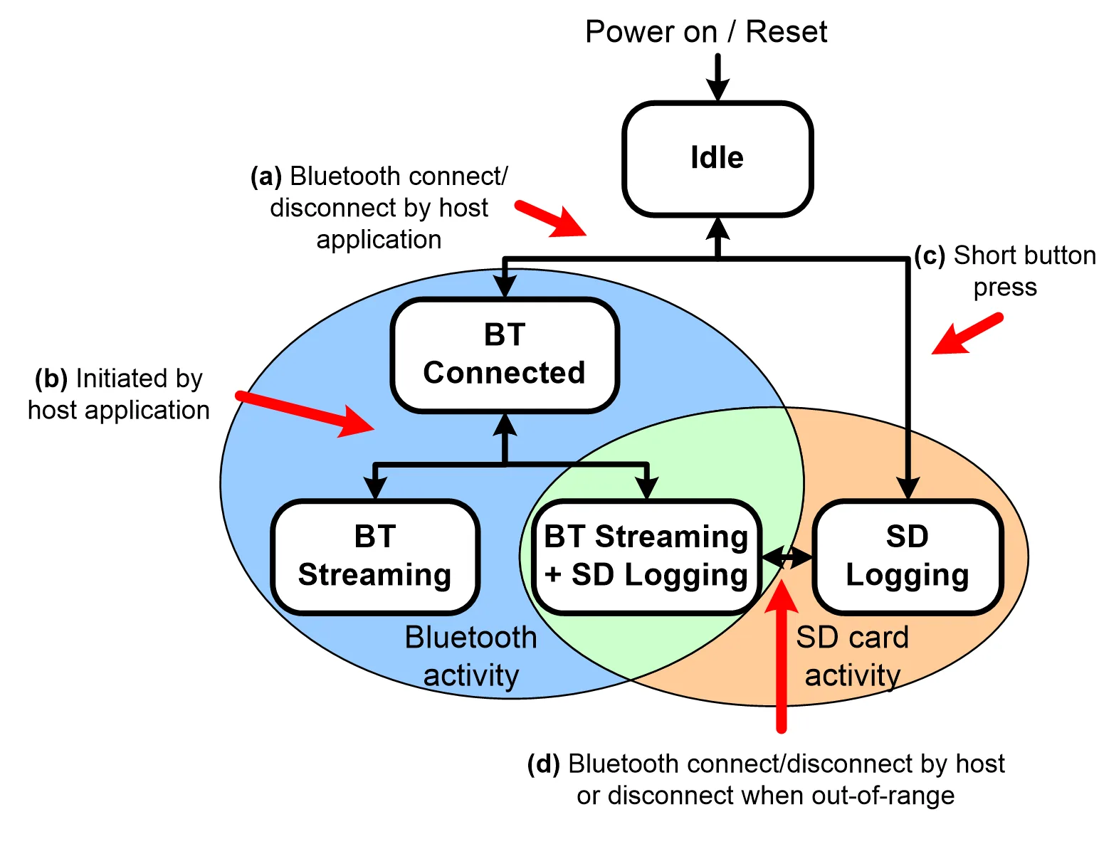
Figure 5‑1 LogAndStream firmware operational hierarchy.
The key feature of the LogAndStream firmware can be viewed at the intersection of the two active branches (green shaded area in Figure 5‑1). From a “host” application, the user can select to stream Shimmer3 sensor data over a Bluetooth connection at the same time as saving it locally to the on‑board microSD card. An instance where this is of key benefit is the case where, in the process of data collection, a Shimmer3 might travel out of range from the “host” device. In this circumstance, the Shimmer3 will continue to save data to the microSD card such that there will be no break in the data recording. Similarly, during normal SD logging operation, continuous Bluetooth streaming is not always desirable or required. By combining Bluetooth support with SD logging capability, the new LogAndStream firmware now facilitates the ability for the user to check the recording activity of a Shimmer3 at any stage during SD logging operation – without interrupting the data recording. It should be noted, however, that the Bluetooth radio on the Shimmer will remain active, regardless of the connection state, so where battery life matters most and streaming is not needed, disable Bluetooth in the configuration (bluetoothDisabled=1).
State 1 – Idle
Note: To use the Bluetooth features of the LogAndStream firmware, the Shimmer3 device must first be paired with a “host” device (e.g., a PC), as outlined in the Shimmer3/3R User Manual.
When a Shimmer3, programmed with LogAndStream firmware, is first powered on or reset, it enters the Idle state. How long it will remain in the Idle state depends on the configuration of a parameter called “Undock Start” (see Section 5.3 for more details).
The ‘paths’ referred to below are indicated in Figure 5‑1.
- To enter BT Connected state, a Bluetooth connection must be initiated by a “host” side application (e.g., ConsensysBASIC). A subsequent disconnection of the Bluetooth connection will send the Shimmer3 back to the Idle state.
There are two ways of reaching the SD Logging state from the Idle state:
If Undock Start is disabled, the device will remain in the Idle state until either a connection is made over the Bluetooth link (i.e., by opening a serial connection), or the user instigates a single button press which will initiate SD logging mode. Similarly, another short button press will terminate SD Logging mode and return the Shimmer3 to Idle state.
If “Undock Start” is enabled, the Shimmer3 will progress directly from Idle mode into SD Logging mode after a power-on or reset condition.
State 2 – BT Connected
In the BT Connected state, the Shimmer3 can process various commands to configure its sensors and sampling parameters, set calibration parameters, send configuration settings back to the “host” (PC, mobile or other) and start sampling. When the Shimmer3 is in the BT Connected, BT Streaming or BT Streaming + SD Logging states, there can be active communication between the Shimmer3 and the host over the Bluetooth serial connection. Packets of bytes are sent in both directions and these can consist of commands, responses or data.
- The host application (e.g., ConsensysBASIC) allows the user to fully configure the Shimmer3 and choose between either BT Streaming or BT Streaming + SD Logging recording modes.
State 3 – BT Streaming
When a command to start BT Streaming is received, the Shimmer3 enters the BT Streaming state and starts sampling data from its sensors and sending that data over the Bluetooth link. This state will continue until one of the following events occurs:
A command to stop logging is received, whereupon the Shimmer3 returns to the BT Connected state.
The serial connection is closed, sending the Shimmer3 back into the idle state.
The Shimmer3 goes out‑of‑range from the “host” device for a certain period (≈ 150 s), whereupon the Shimmer3 will also return to Idle state.
State 4 – BT Streaming + SD Logging
The BT Streaming + SD Logging state can be initiated by using the “host” application (e.g., ConsensysBASIC). When the Shimmer3 enters the BT Streaming + SD Logging state, the Shimmer3 will start sampling data from its sensors and send this data over the Bluetooth link as well as store it locally in raw file format to the microSD card (see Section 5.8).
The Shimmer3 will continue in this mode until one of the following occurs:
A stop logging command is received from the “host”. The Shimmer3 will return to the BT Connected state.
In the event of either a Bluetooth disconnection, the serial port being closed or the Shimmer3 travelling out of range for a certain period (≈ 150 s), the Shimmer3 will automatically enter the SD Logging state (as illustrated by “Path (d)” in Figure 5‑1).
State 5 – SD Logging
In the SD Logging state, the Shimmer3 will continuously read data from its sensors and store this data locally to a raw data file in its on-board microSD card (for more information see Section 5.8). The Shimmer3 will remain open to a Bluetooth connection by a host device, whereupon the Shimmer3 will automatically switch to the BT Streaming + SD Logging state without interruption to the SD logging data stream.
5.2. Real-time clock
Shimmer3R: Shimmer3R keeps the real-world clock across a reset; Shimmer3 loses it at every reset. A Shimmer3R loses the clock only when it loses power completely, and then restarts from 2000-01-01, so host software should still set the clock on every connection. The timekeeping reference describes both generations.
In LogAndStream v0.3.0, the capability to save the ‘real-world’ time from a PC to the Shimmer was introduced. This feature allows simple synchronisation with external events or third party devices by providing a common clock timestamp at the beginning of a logging session. The firmware indicates if the real-time clock has been set on the Shimmer. A blue/green LED indicator on the Shimmer will intermittently flash to indicate to the user that the real time clock has not been set (see Section 2.2 for LED indicators).
The recommended method to set the real-time clock from a PC to a Shimmer device is to use Shimmer ConsensysBASIC or ConsensysPRO software. The time is set via the UART interface with Shimmer Dock or Consensys Base or over Bluetooth in the Consensys software applications. In the case of a user who wishes to set the time outside of a Shimmer application, more details should be sought in the source code for LogAndStream Firmware on the Shimmer github repository2.
Important considerations for real-time clock
Please note the following factors that will affect the reliability of the real-time clock timestamps.
The real-time clock is saved in volatile memory. This means that, if the Shimmer is powered off or reset, the real-world time will be lost.
The real-time clock setting is implemented as a once-off operation that relates the timestamp on the Shimmer’s local clock to the timestamp on the PC. This setting cannot measure or correct for drift of the Shimmer’s internal clock. It is recommended that a data collection session should begin as soon as possible after the real-time clock has been set on the Shimmer. Similarly, if the PC time is being set on multiple devices (Shimmer or third party devices), this should be done on all devices within as short an interval as possible to reduce the effect of clock drift.
Note: It is not critical for the real-time clock setting to be present on the Shimmer in order to record data to the Shimmer’s SD card. The LED sequence will change to the “logging” mode after undock start or push button start and will return to the error LED sequence when logging ceases (see Section 2.2 for LED indicators).
5.3. Starting and stopping logging
5.3.1. Dock (automatic start)
This is the default way for the Shimmer3 to start and stop logging data to the SD card and is enabled if the “Undock Start” option is enabled from ConsensysBASIC or ConsensysPRO or ShimmerCapture (i.e., configuration file line entry: “userbutton=0”). With this configuration, if the Shimmer is powered on or reset while it is not on the dock, the following process will begin immediately:
The Shimmer unit will go into standby mode for up to 3 seconds.
The Shimmer unit will read the configuration file and create the required directories on the SD card.
The Shimmer unit will start logging.
Alternatively, if the Shimmer is powered on or reset while it is on the dock, the three steps above will begin as soon as the Shimmer is removed from the dock.
In either case, logging will continue until the Shimmer unit is reset, powered off, replaced in the dock or the battery runs out.
Repeatedly resetting the Shimmer unit will result in multiple logging sessions on the SD card.
Warning: Please note that it is not recommended to dock the Shimmer unit while it is being configured by the firmware. Ideally, the Shimmer unit should either be powered off or in standby mode whenever it is being placed on the dock.
5.3.2. User button (manually start/stop logging)
This option relies on the orange user button on the Shimmer3 enclosure to start/stop logging.
With this setting, undocking the Shimmer unit or powering it on when it is off the dock will trigger the same steps 1 and 2 as above (i.e., standby for 3 seconds followed by configuration). However, logging will not start until the user button is pressed by the user.
If the user button is pressed while the Shimmer unit is on the dock or Base or connected over Bluetooth, it will have no effect on logging. Otherwise, if the user button is pressed while the Shimmer unit is undocked (and not logging), logging will start immediately.
Logging will continue until one of the following occurs: the user button is pressed, the Shimmer unit is reset, powered off, replaced in the dock, the battery runs out or the Shimmer is told to stop by a host application, whichever happens soonest.
Repeatedly pressing the user button (with Push Button Start enabled) or docking and undocking the Shimmer3 unit (with Undock Start enabled) will result in multiple logging sessions on the SD card.
Note: Do not dock a Shimmer while it is configuring or logging: this can corrupt the SD card’s file system. Power it off, or reset it, before docking.
5.4. Bluetooth streaming
LogAndStream is controlled over Bluetooth with one-byte commands, each followed by any parameters it needs. The Shimmer acknowledges every command it receives. There are four kinds:
- Set commands write configuration: enabled sensors, sampling rate, sensor ranges and rates, calibration parameters and so on.
- Get commands read configuration and status back.
- Action commands start and stop streaming and logging (for example START_STREAMING_COMMAND, START_SDBT_COMMAND), or toggle an LED.
- In-stream commands (GET_STATUS_COMMAND, GET_DIR_COMMAND, GET_VBATT_COMMAND) can be sent while the Shimmer is streaming or logging; their responses arrive among the data packets.
START_STREAMING_COMMAND starts streaming only, and works only while the Shimmer is neither logging nor streaming. START_SDBT_COMMAND starts or resumes streaming and logging together; use it to stream from a Shimmer that is already logging.
Both generations use the same protocol. The complete, current reference, with every command, its bytes, the packet structure, the in-stream responses and the firmware versions that introduced each feature, is the Shimmer3 / Shimmer3R Bluetooth Communication Protocol:
- Opcode table
- Status, ACK/NACK and in-stream responses
- Streaming data flow, including how to separate data packets from in-stream responses
- Command reference
- Connection session workflow
Most users never need these details: Consensys and the Shimmer APIs (Java/Android, C#, Python, MATLAB, LabVIEW) implement the protocol.
Shimmer3R: A Shimmer3R accepts the same commands over both Classic Bluetooth (serial port profile) and Bluetooth Low Energy. It also has commands Shimmer3 ignores, to list, read and delete the files on its SD card over Bluetooth; see the SD file transfer reference.
5.4.1. Bluetooth latency
Delays due to Bluetooth transmission should be taken into account when streaming data, particularly if the data is to be synchronised on the receiver side. In our lab tests the latency was typically about 25 ms and up to about 100 ms, with considerable variation (> 50 ms). These measures result from multiple FIFOs in the data path, as expected in wireless data acquisition systems using conventional computing devices for the data end-points. Actual performance is strongly impacted by end-point system configuration and load.
5.5. Configuration
To use this firmware image, the user must provide the desired configuration parameters of each Shimmer. It is recommended that Shimmer software applications (e.g. ConsensysBASIC or ConsensysPRO) are always used for configuration of sensors for logging, in order to avoid errors introduced in the development of third party software. However, the configuration parameters can be sent to the Shimmer outside of the provided applications, by following the guidelines throughout this section.
 Since v0.4.0, there are three options available for configuring the Shimmer, as outlined in the following section.
5.5.1. Configuring a device
Configuration via Bluetooth
The recommended method of writing the calibration parameters to a Shimmer device, programmed with LogAndStream firmware is to connect via the ConsensysBASIC or ConsensysPRO software application (available from the Shimmer website1) and use the graphical interface to configure the device via a Bluetooth connection. Assuming that LogAndStream v0.4.0 (or later) firmware is programmed on the devices, the new configuration parameters will automatically be written to the appropriate file on the SD card, following the file structure outlined later in this section.
Configuration via UART
Consensys also configures a Shimmer through a Shimmer Dock or Consensys Base, by writing the configuration straight to the Shimmer’s configuration memory (InfoMem). Software of your own can do the same; the configuration memory reference describes every byte, for both generations, and how to tell the firmware that the configuration memory has changed so that it updates sdlog.cfg to match.
Configuration by file
The configuration parameters can be saved in a configuration file, named sdlog.cfg, on the Shimmer’s on-board SD card, from which they will be loaded by the Shimmer at initialisation. Configuration parameters are read from the sdlog.cfg file or from the InfoMem according to the following:
If the ‘InfoMem changed’ flag is set (the configuration memory was written directly; see Configuration via UART), the firmware will read the configuration from InfoMem and will replace any existing sdlog.cfg file.
If the ‘InfoMem changed’ flag is not set, the firmware will look for a configuration file on the SD card. Assuming that the file exists, the configuration will be read and copied to InfoMem.
If the ‘InfoMem changed’ flag is not set and no configuration file exists on the SD card, the firmware will check that there is a valid configuration on the InfoMem. Assuming that there is a valid configuration, a new configuration file will be written with the configuration parameters from InfoMem.
If the ‘InfoMem changed’ flag is not set, no configuration file exists on the SD card, and there is not a valid configuration on the InfoMem, the firmware will indicate an error (see Section 2.2 for LED indicators).
Thus, to change the configuration via the sdlog.cfg file, simply modify the sdlog.cfg file and reboot the Shimmer (there is no need to reprogram).
The configuration file must be saved in the top level directory of the SD card (i.e. not within a subfolder). This file allows configuration of all firmware features, as described throughout the following subsections. Each new line of the configuration file contains a single configuration parameter command. Users should note that the commands should be written exactly as they appear in the following sections so that they will be successfully parsed by the firmware. Any extra whitespaces will cause parsing errors.
If the configuration file has a glitch, such that the firmware cannot read it, the lower LED flashes green fast to warn the user of the error (see Section 2.2 for LED indicators). Note that this error will not occur in the event of parsing errors (e.g. typographical errors, extra whitespace, and repeated commands); it is the user’s responsibility to ensure that the sdlog.cfg file is well-written. Commands with typographical errors and similar will be ignored by the firmware.
It is recommended to use the ConsensysBASIC or ConsensysPRO application for configuration of Shimmer devices, to avoid errors in writing the configuration file. However, the configuration file can be written in any text editor and saved to the SD card without using Shimmer software, by following the guidelines throughout this section.
5.5.2. Enabling sensors
The user may choose which sensors are enabled and disabled on the Shimmer for a particular experiment. These can be enabled or disabled by setting the value of the appropriate bits in InfoMem or by modifying the configuration file. The configuration file should contain a new line for each sensor enable/disable command. If any sensor is not included in the configuration file, it will be assumed to be disabled.
The currently available sensors and their corresponding sdlog.cfg entries are listed in Table 5‑1 for Shimmer3.
Sensor |
Enable command |
Disable command |
|
|---|---|---|---|
Low Noise Accelerometer |
accel=1 |
accel=0 |
|
Gyroscope |
gyro=1 |
gyro=0 |
|
Magnetometer |
mag=1 |
mag=0 |
|
Wide Range Accelerometer |
accel_d=1 |
accel_d=0 |
|
Battery voltage |
vbat=1 |
vbat=0 |
|
External Expansion Channel 7 |
extch7=1 |
extch7=0 |
|
External Expansion Channel 6 |
extch6=1 |
extch6=0 |
|
External Expansion Channel 15 |
extch15=1 |
extch15=0 |
|
Internal Expansion Channel 1 |
intch1=1 |
intch1=0 |
|
Internal Expansion Channel 12 |
intch12=1 |
intch12=0 |
|
Internal Expansion Channel 13 |
intch13=1 |
intch13=0 |
|
Internal Expansion Channel 14 |
intch14=1 |
intch14=0 |
|
GSR |
gsr=1 |
gsr=0 |
|
Pressure & Temperature |
pres=1 |
pres=0 |
|
Pulse/PPG |
intch13=1 and exp_power=1 |
intch13=0 and exp_power=0 |
|
ECG |
24-bit |
exg1_24bit=1 exg2_24bit=1 |
exg1_24bit=0 exg2_24bit=0 |
16-bit |
exg1_16bit=1 exg2_16bit=1 |
exg1_16bit=0 exg2_16bit=0 |
|
EMG |
24-bit |
exg1_24bit=1 |
exg1_24bit=0 |
16-bit |
exg1_16bit=1 |
exg1_16bit=0 |
|
Bridge Amplifier |
br_amp=1 |
br_amp=0 |
|
Note: To enable the ExG Test Signal to verify the correct operation of the Shimmer3 ECG or EMG module, see the ECG User Guide or the EMG User Guide, available on our website3.
Shimmer3R: the sensors, and the keys for the analogue channels, differ; see Table 5‑1R.
| Sensor | Enable command | Notes |
|---|---|---|
| Low-Noise Accelerometer (LSM6DSV) | accel=1 |
Same key as Shimmer3 |
| Gyroscope (LSM6DSV) | gyro=1 |
Same key as Shimmer3 |
| Magnetometer (LIS2MDL) | mag=1 |
Same key as Shimmer3 |
| Wide-Range Accelerometer (LIS2DW12) | accel_d=1 |
Same key as Shimmer3 |
| High-G Accelerometer (ADXL371) | accel_alt=1 |
Shimmer3R only. Fitted to the IMU (SR31) only |
| Pressure & Temperature (BMP390 or BMP581) | pres=1 |
Same key as Shimmer3 |
| Battery voltage | vbat=1 |
Same key as Shimmer3 |
| External Expansion Ext A0 | extch0=1 |
Replaces Shimmer3 extch7 |
| External Expansion Ext A1 | extch1=1 |
Replaces Shimmer3 extch6 |
| External Expansion Ext A2 | extch2=1 |
Replaces Shimmer3 extch15 |
| Internal Expansion Int A0 | intch0=1 |
Replaces Shimmer3 intch12 |
| Internal Expansion Int A1 | intch1=1 |
Replaces Shimmer3 intch13. On Shimmer3, intch1 is a different channel, Int A1, which on Shimmer3R is Int A3 |
| Internal Expansion Int A2 | intch2=1 |
Replaces Shimmer3 intch14 |
| Internal Expansion Int A3 | intch3=1 |
Replaces Shimmer3 intch1 |
| GSR | gsr=1 |
Same key. Turns Int A3 (intch3) off |
| Pulse/PPG (GSR+ board) | intch1=1 and exp_power=1 |
Shimmer3 uses intch13. PPG can also be wired to Int A0 (intch0) |
| ECG, 24-bit | exg1_24bit=1, exg2_24bit=1 |
Same keys. Turns Int A2 and Int A3 off |
| ECG, 16-bit | exg1_16bit=1, exg2_16bit=1 |
Same keys |
| EMG, 24-bit | exg1_24bit=1 |
Same key |
| EMG, 16-bit | exg1_16bit=1 |
Same key |
| Bridge Amplifier | br_amp=1 |
Same key (str=1 is also accepted). Turns Int A1 and Int A2 off |
Differences from Shimmer3:
- The seven expansion ADC channels have new keys, named after the channels’ Shimmer3R names. A Shimmer3 file’s
extch7,extch6,extch15,intch12,intch13andintch14lines are ignored by a Shimmer3R. intch1exists on both but means a different channel. A Shimmer3 file withintch1=1enables Int A1 on a Shimmer3R, the channel a Shimmer3 calls Int A13, not the GSR-shared channel.accel_altenables the high-g accelerometer. A Shimmer3R ignores the Shimmer3 keysaccel_mpuandmag_mpu.- The microphone has no configuration file key, and the Shimmer3R does not support it.
- On a Shimmer3R, the ExG board does not need
exp_power=1. Consensys sets it anyway, and it does no harm.
Table 5‑1R Sensor enable/disable commands for Shimmer3R
Certain combinations of sensors cannot be enabled simultaneously due to hardware or firmware restrictions. A table listing the Shimmer3 and Shimmer3R sensor conflicts is given in Table 9‑1 in Appendix 9.4.
Sensor parameters
See Table 5‑2 (Shimmer3) and Table 5‑2R (Shimmer3R) for sensor configuration parameters and corresponding configuration file commands.
Parameter |
Example command |
Valid options |
Default |
|||
|---|---|---|---|---|---|---|
Accel range |
acc_range=0 |
LSM303DLHC |
LSM303AHTR |
0 (± 2.0 g) |
||
0 (± 2.0 g) |
0 (± 2.0 g) |
|||||
1 (± 4.0 g) |
2 (± 4.0 g) |
|||||
2 (± 8.0 g) |
3 (± 8.0 g) |
|||||
3 (± 16.0 g) |
1 (± 16.0 g) |
|||||
Gyro range |
gyro_range=1 |
MPU9150 |
MPU9250 |
1 (±500 dps) |
||
0 (±250 dps) 1 (±500 dps) 2 (±1000 dps) 3 (±2000 dps) |
||||||
Mag range |
mg_range=1 |
LSM303DLHC |
LSM303AHTR |
1 (±1.3 Ga) or 0 (± 49.152Ga) depending on board type |
||
1 (± 1.3 Ga) |
0 (± 49.152Ga) |
|||||
2 (± 1.9 Ga) |
||||||
3 (± 2.5 Ga) |
||||||
4 (± 4.0 Ga) |
||||||
5 (± 4.7 Ga) |
||||||
6 (± 5.6 Ga) |
||||||
7 (± 8.1 Ga) |
||||||
Accel internal data rate |
acc_internal_rate=1 |
LSM303DLHC |
LSM303AHTR |
5 (100 Hz) or 4 (100Hz) depending on board type |
||
0 (power down) |
0 (power down) |
|||||
1 (1.0 Hz) |
1 (12.5 Hz) |
|||||
2 (10 Hz) |
2 (25 Hz) |
|||||
3 (25 Hz) |
3 (50 Hz) |
|||||
4 (50 Hz) |
4 (100 Hz) |
|||||
5 (100 Hz) |
5 (200 Hz) |
|||||
6 (200 Hz) |
6 (400 Hz) |
|||||
7 (400 Hz) |
7 (800 Hz) |
|||||
8 (1.620 kHz) |
8 (1.600 kHz) |
|||||
9 (1.344 kHz) |
9 (3.200 kHz) |
|||||
10 (6.400 kHz) |
||||||
Gyro internal data rate |
gyro_samplingrate=0 |
MPU9150 |
MPU9250 |
155 (51.28 Hz) |
||
0 – 255 (8000/(value+1) Hz) |
||||||
Mag internal data rate |
mg_internal_rate=0 |
LSM303DLHC |
LSM303AHTR |
6 (75 Hz) Or 3 (100.0 Hz) depending on board type |
||
0 (0.75 Hz) |
0 (10.0 Hz) |
|||||
1 (1.5 Hz) |
1 (20.0 Hz) |
|||||
2 (3.0 Hz) |
2 (50.0 Hz) |
|||||
3 (7.5 Hz) |
3 (100.0 Hz) |
|||||
4 (15.0 Hz) |
||||||
5 (30.0 Hz) |
||||||
6 (75.0 Hz) |
||||||
7 (220.0 Hz) |
||||||
Accel Low Power Mode |
acc_lpm=0 |
0 (disabled) 1 (enabled) |
0 (disabled) |
|||
Accel High Res Mode |
acc_hrm=0 |
0 (disabled) 1 (enabled) |
0 (disabled) |
|||
GSR range |
gsr_range=0 |
0 (8 kΩ – 63 kΩ) 1 (63 kΩ – 220 kΩ) 2 (220 kΩ – 680 kΩ) 3 (680 kΩ – 4.7 MΩ) 4 (Auto Range) |
4 (Auto Range) |
|||
Pressure Resolution |
pres_bmp180_prec=0 |
0 (Low) 1 (Standard) 2 (High) 3 (Very High) |
0 (Low) |
|||
Table 5‑2 Sampling configuration options for Shimmer3
Shimmer3R: see Table 5‑2R. Several keys are shared with Shimmer3 but encode different values.
Values are written in decimal. Where the table says what other values give, the firmware substitutes that value. Elsewhere, values outside the list are not checked. In neither case is an error reported.
| Parameter | Example command | Valid options | Default |
|---|---|---|---|
| Low-noise accel range (LSM6DSV) | accel_ln_range=0 |
0 (± 2 g) 1 (± 4 g) 2 (± 8 g) 3 (± 16 g) |
0 (± 2 g) |
| Gyro range (LSM6DSV) | gyro_range=2 |
0 (± 125 dps) 1 (± 250 dps) 2 (± 500 dps) 3 (± 1000 dps) 4 (± 2000 dps) 5 (± 4000 dps) Other values give 2 |
2 (± 500 dps) |
| Gyro and low-noise accel data rate (LSM6DSV, one rate shared by both) | gyro_samplingrate=5 |
0 (power-down) 1 (1.875 Hz) 2 (7.5 Hz) 3 (15 Hz) 4 (30 Hz) 5 (60 Hz) 6 (120 Hz) 7 (240 Hz) 8 (480 Hz) 9 (960 Hz) 10 (1920 Hz) 11 (3840 Hz) 12 and above give 5 |
5 (60 Hz) |
| Wide-range accel range (LIS2DW12) | acc_range=0 |
0 (± 2 g) 1 (± 4 g) 2 (± 8 g) 3 (± 16 g) |
0 (± 2 g) |
| Wide-range accel data rate (LIS2DW12) | acc_internal_rate=5 |
0 (power-down) 1 (12.5 Hz; 1.6 Hz in low-power mode) 2 (12.5 Hz) 3 (25 Hz) 4 (50 Hz) 5 (100 Hz) 6 (200 Hz) 7 (400 Hz) 8 (800 Hz) 9 (1600 Hz) In low-power mode, 7 to 9 give 200 Hz |
5 (100 Hz) |
| Wide-range accel high-performance mode (LIS2DW12) | acc_hrm=1 |
0 (low-power mode, as set by acc_lpm)1 (high-performance mode, 14-bit) |
1 (high-performance) |
Wide-range accel low-power mode (LIS2DW12; applies only when acc_hrm=0) |
acc_lpm=0 |
0 (low-power mode 1, 12-bit) 1 (low-power mode 2, 14-bit) 2 (low-power mode 3, 14-bit) 3 (low-power mode 4, 14-bit) Other values give 0 |
0 |
| Mag data rate (LIS2MDL) | mg_internal_rate=3 |
0 (10 Hz) 1 (20 Hz) 2 (50 Hz) 3 (100 Hz) Higher values give 3 |
3 (100 Hz) |
| High-g accel data rate (ADXL371, IMU only) | accel_alt_rate=0 |
0 (320 Hz) 1 (640 Hz) 2 (1280 Hz) 3 (2560 Hz) |
0 (320 Hz) |
| Pressure resolution (BMP390) | pres_bmp390_prec=0 |
0 (Ultra Low: no oversampling) 1 (Low: 2x) 2 (Standard: 4x) 3 (High: 8x) 4 (Ultra High: 16x) 5 (Highest: 32x) Other values give 0 |
0 |
| Pressure resolution (BMP581) | pres_bmp581_prec=0 |
0 (Lowest Power: 1x) 1 (Low: 2x) 2 (Standard: 4x) 3 (High: 8x) 4 (High Res: 16x) 5 (Very High Res: 32x) 6 (Ultra High Res: 64x) 7 (Highest Res: 128x) Other values give 0 |
0 |
| GSR range | gsr_range=4 |
0 (8 kΩ – 63 kΩ) 1 (63 kΩ – 220 kΩ) 2 (220 kΩ – 680 kΩ) 3 (680 kΩ – 4.7 MΩ) 4 (Auto Range) Values above 4 give 4 |
4 (Auto Range) |
| Expansion board power | exp_power=0 |
0 (off) 1 (on) |
0 (off) |
Notes:
- Sensor data rates must be at least the sampling rate. When a Shimmer3R reads the configuration, it checks each enabled accelerometer, gyroscope and magnetometer. If a sensor’s data rate is below the sampling rate, the firmware raises it to the lowest rate that keeps up. The magnetometer stops at its 100 Hz maximum. The corrected value is written back to sdlog.cfg.
- The gyroscope and low-noise accelerometer share one data rate,
gyro_samplingrate. A Shimmer3R has no separate low-noise accel rate. gyro_rangecodes differ from Shimmer3. On a Shimmer3R, 1 means ±250 dps. On a Shimmer3, 1 means ±500 dps.- The two pressure keys are interchangeable. A Shimmer3R reads either key and applies the value to the sensor that is fitted. It writes the key for that sensor. The BMP581 replaced the BMP390 from the
-2board revisions. The pressure sensor’s output rate is not configurable: the firmware sets it from the sampling rate. - Ranges that cannot be changed have no key. They are the magnetometer at ±49.152 Ga and the high-g accelerometer at ±200 g.
- Shimmer3 keys that a Shimmer3R ignores:
mg_range,accel_alt_rangeandpres_bmp180_prec/pres_bmp280_prec. The Shimmer3 keysacc_lpm,acc_hrm,acc_internal_rate,acc_range,gyro_range,gyro_samplingrateandmg_internal_rateare reused, but with the Shimmer3R encodings above.
Table 5‑2R Sampling configuration options for Shimmer3R
Note: See ECG User Guide or EMG User Guide for ExG gain and rate settings.
Experiment settings
In addition to the sensor-specific parameters listed in the previous subsections, configuration parameters for an experiment or data collection can be configured using the commands in Table 5‑3. Further details describing these parameters are provided below the table.
Parameter |
Example command |
Valid options |
Default |
|---|---|---|---|
Sampling rate (in Hz) |
sample_rate=51.2 |
0, …, 1024 |
51.2 |
Number of Shimmers |
Nshimmer=12 |
positive integer value:0, …, 255 |
0 |
Shimmer ID number |
myid=1 |
positive integer value: 0, …, Nshimmer |
0 |
Shimmer name |
shimmername=shimmer1 |
string with up to 12 characters |
Shimmer_ and the last 4 characters of the Bluetooth address |
Experiment ID |
experimentid=expid |
string with up to 12 characters |
DefaultTrial |
Configuration ID |
configtime=1234567890 |
any 32-bit signed integer value |
0 |
User button |
user_button_enable=1 |
0 (disabled) 1 (enabled) |
1 |
SD Error |
sd_error_enable=1 |
0 (disabled) 1 (enabled) |
1 |
Table 5‑3 Logging configuration options The Sampling rate is the frequency at which sampling should be performed. The actual sampling rate may not be exactly equal to this parameter, because the sampling period is a whole number of ticks of a 32768 Hz clock. Consensys and the Shimmer APIs choose the number of ticks (the divider) as 32768/Fs rounded down, or rounded up when it falls within 0.05 below a whole number. The true sampling rate is then:
True Fs = 32768/divider
For example, 500 Hz gives a divider of 65 (32768/500 = 65.536), so the true rate is 504.12 Hz; 100 Hz gives 327 and 100.21 Hz. Rates such as 51.2, 128, 256, 512 and 1024 Hz divide 32768 exactly.
Shimmer3R: Shimmer3R’s sampling period is an even number of ticks, so when the divider is odd it samples at 32768/(divider − 1): 512 Hz for 500 Hz, 100.52 Hz for 100 Hz and 252.06 Hz for 250 Hz. The rate recorded in the configuration and the data file header is still the requested one. Use the sample timestamps, not the nominal rate, when timing matters.
Number of Shimmers and Shimmer ID number are used to describe the total number of Shimmers in an experiment and the ID number of each individual Shimmer. These parameters do not have any explicit function in firmware.
The Shimmer name parameter allows the user to specify a meaningful name for each device. It is used by the firmware to name the data directories on the SD card. For more information on the directory structure, see Section 5.8.1.
The Experiment ID parameter allows the user to specify a meaningful name for an experiment. It is used by the firmware to name the data directories on the SD card. For more information on the directory structure, see Section 5.8.1.
The Configuration ID is a numeric identifier for the experiment. It typically refers to the date and/or time at which the configuration file was created (but users may choose any valid numeric value that is meaningful to them4). It is appended to the experiment ID name in the data directories to allow the user to identify different experiments in the case that the same experiment ID name is used multiple times. It is vital that this parameter is equal for all Shimmers in the experiment if SD sync is enabled (Section 5.7).
The User button refers to the button on the baseboard which is accessible by pressing the circular orange button on the Shimmer3 enclosure. If the button is enabled, then logging will begin when the user button is pressed. Logging will finish when any one of the following happens: the user button is pressed again; the Shimmer battery runs out; the Shimmer is placed on the Shimmer Dock.
The SD Error is a flag (introduced in LogAndStream_v0.9.0) which enables/disables the SD-error LED sequence (the lower LED flashing green fast), which shows should the Shimmer have issues accessing the SD card or if there is no SD card present.
5.6. Calibration parameters
Each Shimmer stores calibration for its inertial sensors: an offset, a sensitivity and an alignment matrix for each sensor and range. The firmware never applies calibration to the data: streamed and logged samples are always raw, and the calibration is written into each SD data file’s header, so that Consensys or your own software can calibrate the data afterwards. The other channels (analogue inputs, GSR, ExG, bridge amplifier, battery) use fixed conversions and have no stored calibration.
5.6.1. Providing calibration information
Calibrate the sensors in Consensys (Calibrating the Sensors in the IMU User Guide). Consensys sends the new parameters to the Shimmer over Bluetooth, and the firmware stores them as described below. Editing the calibration file by hand is not recommended.
Note: The calibParams.ini file used by early firmware is no longer read by Shimmer3 or Shimmer3R firmware.
5.6.2. Where calibration is stored
| Copy | Contents |
|---|---|
| Configuration memory (InfoMem) | Calibration for the currently selected range of each sensor. It survives power-off |
SD card file /Calibration/calib_XXXX |
Every range of every sensor, each with a timestamp. XXXX is the last four characters of the Shimmer’s Bluetooth address, as on its label (for example calib_5A1C), so one card can hold files for several Shimmers. It is a binary file |
| SD data file header | The calibration in force for the selected ranges when the file was created, with timestamps |
Table 5‑4 Calibration copies on the SD card
The firmware uses the folder Calibration (or an existing calibration) at the top level of the card, and creates it if neither exists. It keeps the copies in step:
- At power-on, undocked, with an SD card: if the calibration file exists, it is loaded and replaces the configuration memory. If it does not, it is created from the configuration memory, with the firmware defaults for any range that has no stored calibration.
- Calibration sent over Bluetooth while undocked: the configuration memory, the header for the next data file and the calibration file are all updated at once.
- Calibration sent over Bluetooth while docked: the configuration memory is updated at once, and the calibration file when the Shimmer is undocked (or, if it is logging then, when logging stops).
Note: If a docked Shimmer is switched off before it is undocked, its calibration file is not updated, and the older file then replaces the new calibration the next time it is read. Undock the Shimmer after calibrating it.
A sensor whose calibration timestamp is all zeros is using the firmware default.
5.6.3. Default calibration parameters
The firmware uses these defaults until a sensor is calibrated. They are nominal datasheet values, so calibrate each Shimmer for accurate data. Offsets are in raw counts, for all axes. Sensitivities are in LSB/(m/s²) for the accelerometers, LSB/(°/s) for the gyroscopes and LSB/Ga for the magnetometers. Alignment matrices are given row by row. The sensors’ ranges and datasheet sensitivities are in Shimmer3 Capabilities and Shimmer3R Capabilities in the IMU User Guide.
Shimmer3: current firmware (LogAndStream v1.00.003 and later) uses the same defaults on every board, whichever sensor variant is fitted:
| Sensor | Offset | Sensitivity | Alignment |
|---|---|---|---|
| Low-noise accelerometer | 2047 | 83 | [0 −1 0; −1 0 0; 0 0 −1] |
| Gyroscope | 0 | ±250 °/s: 131 · ±500 °/s: 65.5 · ±1000 °/s: 32.8 · ±2000 °/s: 16.4 | [0 −1 0; −1 0 0; 0 0 −1] |
| Wide-range accelerometer | 0 | ±2 g: 1631 · ±4 g: 815 · ±8 g: 408 · ±16 g: 135 | [−1 0 0; 0 1 0; 0 0 −1] |
| Magnetometer (X / Y / Z) | 0 | ±1.3 Ga: 1100/1100/980 · ±1.9 Ga: 855/855/760 · ±2.5 Ga: 670/670/600 · ±4.0 Ga: 450/450/400 · ±4.7 Ga: 400/400/355 · ±5.6 Ga: 330/330/295 · ±8.1 Ga: 230/230/205 | [−1 0 0; 0 1 0; 0 0 −1] |
Table 5‑5 Shimmer3 default calibration parameters
These are the values for the first-generation sensors (KXRB5-2042, LSM303DLHC). On boards with a KXTC9-2050 low-noise accelerometer, or an LSM303AHTR or ICM-20948 wide-range accelerometer and magnetometer, they are only approximate: calibrate those boards before use.
Note: Firmware up to LogAndStream v0.16.003 chose defaults by the sensors fitted: KXTC9-2050 offset 2253 and sensitivity 92; LSM303AHTR accelerometer 1671 / 836 / 418 / 209 with alignment [0 −1 0; 1 0 0; 0 0 −1]; LSM303AHTR magnetometer 667.
Shimmer3R:
| Sensor | Offset | Sensitivity | Alignment |
|---|---|---|---|
| Low-noise accelerometer (LSM6DSV) | 0 | ±2 g: 1672 · ±4 g: 836 · ±8 g: 418 · ±16 g: 209 | [−1 0 0; 0 1 0; 0 0 −1] |
| Gyroscope (LSM6DSV) | 0 | ±125 °/s: 229 · ±250 °/s: 114 · ±500 °/s: 57 · ±1000 °/s: 29 · ±2000 °/s: 14 · ±4000 °/s: 7 | [−1 0 0; 0 1 0; 0 0 −1] |
| Wide-range accelerometer (LIS2DW12) | 0 | ±2 g: 1671 · ±4 g: 836 · ±8 g: 418 · ±16 g: 209 | [0 −1 0; −1 0 0; 0 0 −1] |
| Magnetometer (LIS2MDL) | 0 | ±49.152 Ga: 667 | [−1 0 0; 0 −1 0; 0 0 −1] |
| High-g accelerometer (ADXL371, IMU only) | 10 | 1 (placeholder) | [0 1 0; 1 0 0; 0 0 −1] |
Table 5‑5R Shimmer3R default calibration parameters
The ADXL371’s default is a placeholder that does not give usable values; calibrate it before use.
The byte layout of the calibration file, the configuration memory and the SD header is in the calibration reference.
5.7. Synchronised logging across several Shimmers
Each Shimmer keeps time with its own crystal, which drifts with temperature and component tolerance. Setting the real-world clock (Section 5.2) puts every Shimmer on the PC’s time when the clock is set, but it cannot correct drift after that. Over a long session, Shimmers logging side by side can end up a noticeable fraction of a second apart.
SD sync measures that drift while the session runs. One Shimmer is the centre, and the others are nodes. Throughout logging, the centre connects to each node over Bluetooth and they compare clocks. Each node records its offset from the centre in its own data file. Afterwards, software uses those offsets to place every node’s data on the centre’s timeline.
Note: SD sync was previously a feature of the SDLog firmware, which is retired. LogAndStream includes it on both Shimmer3 and Shimmer3R. Earlier documents and some configuration keys call the centre the master and the nodes slaves.
SD sync is in LogAndStream from v1.00.002 on Shimmer3 and from v1.00.029 on Shimmer3R, and is configured with Consensys 2.0.0 or later.
No clock is changed. Every Shimmer logs against its own clock, and its timestamps are written as it read them. Sync only records the offsets; aligning the data is done afterwards, by Consensys or by your own software (Section 5.7.5).
5.7.1. Clock drift
Shimmer-to-Shimmer clock drift varies and can reach 12 µs per second: 0.72 ms a minute, 43 ms an hour, about 1 s a day. Synchronised logging corrects for it; without it, align recordings from different Shimmers over long sessions with care.
5.7.2. Before you start
- Bluetooth is reserved for sync. A Shimmer with sync enabled uses its radio for Shimmer-to-Shimmer communication. It cannot be used to stream to a host at the same time, so SD sync is for sessions that log to the SD card.
- Up to 20 nodes can sync with one centre.
- Range: every node must be within Bluetooth range of the centre, about 10 m with a clear line of sight. Bodies block Bluetooth well, so avoid placements where the wearer’s body is between the centre and a node.
- Set the real-world clock on the centre, and preferably on every Shimmer, before the session. The nodes align to whatever the centre’s clock reads. A centre whose clock is not set gives a consistent timeline, but not the real time.
- One button press no longer starts every Shimmer. SDLog‘s single-touch start is not supported by LogAndStream, and the configuration file’s
singletouchkey has no effect. Start each Shimmer as described in Section 5.3.
5.7.3. Configuring sync
The recommended way to set up sync is in Consensys, which writes the same settings to every Shimmer in the session: which Shimmer is the centre, the list of nodes, and the estimated length of the session.
The estimated experiment length sets how often the centre syncs with the nodes. The intended settings are:
| Setting | Use for sessions of |
|---|---|
| Short | under an hour |
| Medium | one to three hours |
| Long | more than three hours |
Table 5‑6 Estimated experiment length settings
In a short session, the centre does not keep retrying a node it cannot reach, so a node that is out of range when the centre tries it can end up with no offset.
Sync can also be set in the configuration file sdlog.cfg (Section 5.5), with these keys:
| Key | Meaning |
|---|---|
sync=1 |
Enable SD sync |
iammaster=1 |
This Shimmer is the centre. Omit it, or set it to 0, on the nodes |
center= |
The centre’s Bluetooth address |
node= |
A node’s Bluetooth address. Repeat the line once per node |
est_exp_len= |
Estimated experiment length, in minutes |
Table 5‑7 Sync keys in sdlog.cfg
The complete list of keys is in the SD card format reference.
5.7.4. During the session
At intervals set by the estimated experiment length, the centre connects to each node in turn. The two exchange 50 clock readings, and the node keeps the reading with the least radio delay as its offset. The first exchange with each node is a warm-up and is thrown away, so a node has an offset only after its second exchange. Syncing 20 nodes takes several minutes, even when every node answers first time.
The upper LED shows sync status: green, slow, while logging; blue, flashing fast, during each sync exchange; and green and blue alternating on a node that has not had its first sync yet. Upper LED: Bluetooth disabled, or SD-sync mode lists every pattern.
5.7.5. Aligning the data
Consensys aligns synchronised data when it imports the session’s files from the SD cards, and it is the recommended way to do so.
To align the data in your own software:
- Read each node’s offsets. With sync enabled, the node records in its data file the offset between its clock and the centre’s clock that each sync exchange measured, with its sign (whether the node’s clock is ahead or behind). Most blocks of the file hold no new offset; a block that follows a sync exchange holds the offset that exchange measured. Where the offsets sit in the file, and how they are encoded, is in the SD sync reference and the SD card format reference.
- Pair each valid offset with a time: the timestamp of the first sample in its block.
- Apply the sign. Take the offset as positive when the node’s clock is ahead of the centre’s and negative when it is behind.
- Interpolate the offsets across the node’s samples, so that every sample has an offset estimate (Figure 5‑2 and Figure 5‑3). Linear interpolation is adequate. Each measured offset is the true offset plus some radio delay, so a fit along the lower edge of the measured offsets is better than a least-squares fit through them.
- Convert the node’s timestamps to its real-world clock, as described in the timekeeping reference. The centre’s clock readings, and so the offsets, are real-world clock times.
- Subtract each sample’s offset from its timestamp. The result is the sample’s time on the centre’s clock.
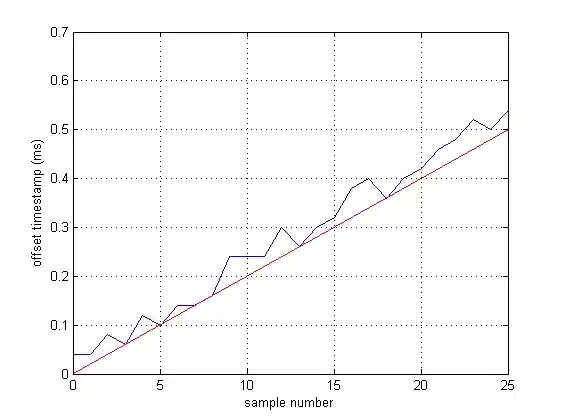
Figure 5‑2 Measured offsets (blue) and a fit along their lower edge (red)
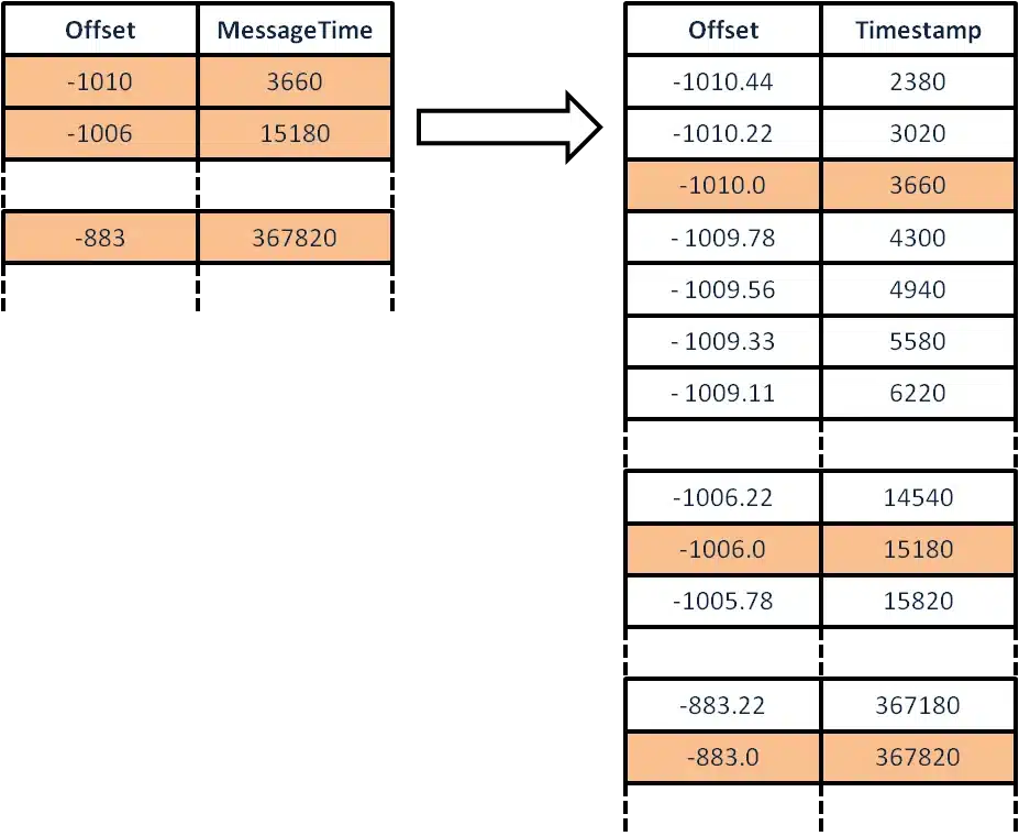
Figure 5‑3 Interpolating the valid offsets to give one for every sample
The byte layout of the data file, including where the offset fields sit, is in the SD card format reference, and the sync procedure itself in the SD sync reference.
5.7.6. Synchronising with an external system
To relate Shimmer data to another system, such as a motion capture system, feed that system’s trigger signal into one Shimmer and log it alongside the data. The trigger then marks, in the Shimmer data, the moments the other system marked in its own.
Connect the trigger. Use one Shimmer as the trigger Shimmer, fitted with an External Expansion Board or a PROTO3 Deluxe, and connect the external system’s trigger output to one of its analog inputs.
Note: The Shimmer’s ADC accepts at most 3 V. A trigger signal above 3 V must be stepped down, for example with a resistor divider, before it reaches the Shimmer.
Set the real-world clock on every Shimmer (Section 5.2), by docking them in a Shimmer Dock or Consensys Base with Consensys. This puts every Shimmer on the PC’s clock.
For long sessions, also use SD sync (Section 5.7), so that the Shimmers’ drift is measured and can be corrected. Start every Shimmer logging, and wait until each node’s LED shows that it has its first offset (Section 5.7.4). For a short session, the real-world clock alone may be close enough.
Send triggers from the external system, for example at the start and end of each recording. The trigger Shimmer records each one, with its timestamp, in the channel the trigger is connected to.
Afterwards, find the triggers in the trigger Shimmer’s data, and use their timestamps to cut the matching stretches from every other Shimmer’s data. This works because all the Shimmers are on one clock.
The trigger is timed to within one sample of the trigger Shimmer: about 20 ms at 51.2 Hz, and about 1 ms at 1024 Hz. Use a higher sampling rate on the trigger Shimmer when the timing matters.
5.8. Reading the SD card data
It is recommended that the Consensys software (available from the Shimmer website1) be used to read the data from the SD card. However, using the following guidelines, the user may use their platform of choice to read and parse the data.
5.8.1. SD card directory structure
/
├── sdlog.cfg                          configuration file (Section 5.5)
├── Calibration/
│   └── calib_<last 4 characters of the Bluetooth address>
└── data/
    └── <experiment ID>_<configuration time>/
        └── <Shimmer name>-<NNNN>/      one folder per logging session
            ├── 000                    data files
            ├── 001
└── ...- The firmware creates a folder called data at the top level of the card if it does not exist.
- Inside it, each trial has a folder named from the experiment ID and the configuration time set by Consensys. Every Shimmer configured for the same trial uses the same name, which is what lets the cards be combined afterwards. The default experiment ID is DefaultTrial.
- Each time logging starts, a new session folder is created, named from the Shimmer’s name (by default Shimmer_ and the last four characters of its Bluetooth address) and a four-digit number that counts up: Shimmer_5AA4-0000, then Shimmer_5AA4-0001, and so on.
- Data is written to files named 000, 001 and so on, with no extension. A new file is started after every hour of logging.
Shimmer3R: A Shimmer3R does not log while it is docked or connected to USB, because the card is handed to the PC. Its files can also be read over Bluetooth without docking. In the data, Shimmer3R orders some channels differently and sends pressure before temperature; Consensys and the Shimmer APIs handle this.
5.8.2. The data file format
Each data file starts with a header that records the configuration it was logged with: the enabled sensors and their settings, the sampling rate, the calibration parameters, the Shimmer’s identity and firmware version, and the time logging started. The samples follow, in blocks.
The format is described byte by byte in the SD card format reference, which covers both generations and is kept up to date with the firmware. Points that commonly catch out a parser:
- The header is 256 bytes on Shimmer3 and 384 bytes on Shimmer3R.
- The samples are written in blocks of up to 512 bytes, and a sample never straddles two blocks, so a block is usually a little shorter than 512 bytes. When SD sync is enabled, each block also starts with a 9-byte offset field (Section 5.7.5).
- Turning the timestamps into real time is described in the timekeeping reference.
Note: Earlier editions of the LogAndStream manual described the header for firmware v0.11. Many of its fields have changed since; use the reference above.
5.9. Programming a Shimmer
Consensys programs LogAndStream onto a Shimmer, and can install other firmware images (.txt files) from its Other tab. Place the Shimmer, switched on, in a Shimmer Dock or Consensys Base, select it in MANAGE DEVICES and click FIRMWARE. The Consensys User Guide shows the steps. By default Consensys keeps the Shimmer’s configuration and calibration through an update. If a Shimmer misbehaves after an update, reprogram it with Reload configuration after firmware write unticked, which restores its factory settings. This also resets its calibration to the defaults, so calibrate it again afterwards; see Reload configuration after firmware write in the Consensys User Guide.
Consensys needs no other software to program either generation. It programs a Shimmer3 in a Shimmer Dock or Consensys Base6/Base15.
Shimmer3R: Consensys programs a Shimmer3R in a Shimmer Dock or Consensys Base6/Base15, or connected directly with a USB-C cable (LogAndStream v1.00.58 or later; see the Consensys User Guide). It restarts the Shimmer3R into its bootloader itself, and the Shimmer3R restarts into the new firmware when programming is finished. Shimmer3R firmware images are separate from Shimmer3 images, and their version numbers are independent: a Shimmer3R version cannot be compared with a Shimmer3 one.
Warning: Shimmer3 and Shimmer3R use different firmware. Programming one with the other’s firmware can leave it unrecoverable without returning it to us.
5.10. Firmware Development
LogAndStream is open source. Each repository’s README gives its toolchain and build steps:
- Shimmer3 (MSP430F5437A, built with TI Code Composer Studio): https://github.com/ShimmerResearch/shimmer3-firmware
- Shimmer3R (STM32U5, built with STM32CubeIDE, programmed and debugged over SWD): https://github.com/ShimmerResearch/shimmer3r-firmware
- The behaviour both share (logging, streaming, configuration, calibration, LEDs, button, clock) is one library, https://github.com/ShimmerResearch/log-and-stream-common. Its
docs/folder is the reference for the Bluetooth protocol, the configuration memory, the data formats and building and programming the firmware.
Clone with git clone --recurse-submodules, because both firmware repositories carry the shared library as a submodule. A firmware image you build can be programmed with Consensys (Programming a Shimmer), or with a debug probe: the Shimmer3 JTAG Developer Board for Shimmer3.
6. Hardware
This section provides an overview of the Shimmer hardware architecture and discusses the hardware sub-systems contained within. For Shimmer3 mainboard detail and pin-out information, see the Shimmer3/3R Hardware Developer Reference.
6.1. Shimmer Hardware Overview
The Shimmer3 mainboard is built around a low-power MSP430F5437A processor, which reads the sensors, logs to the microSD card and streams over Bluetooth. Its block diagram, and how the processor connects to the sensors, the radio and the expansion connectors, are in the Shimmer3/3R Hardware Developer Reference.
6.2. Hardware Sub-System Detail
Functional descriptions of communication, microSD storage and power subsystems are presented in this section. Lower-level component information is in the Shimmer3/3R Hardware Developer Reference. Vendor datasheets and application notes are the best sources of detailed operational information, training material and errata on components designed into Shimmer.
6.2.1. Radio Communication
Shimmer3 streams over Bluetooth Classic, with the Serial Port Profile. Early units carry the Roving Networks RN-42, a Class 2 module with a range of more than 10 m; later units carry the Microchip RN4678, which adds Bluetooth Low Energy. The module talks to the processor over a UART at 115.2 kbaud by default. The Shimmer3/3R Hardware Developer Reference describes the radio in more detail.
6.2.2. MicroSD Card Storage
MicroSD Card Socket
The Shimmer3 mainboard contains a microSD card socket to incorporate extra memory resources. For Shimmer compatibility, the microSD card chosen must implement 1-bit SPI mode. See Choosing a microSD card below. A compatible SD card is shipped with each Shimmer3.
Choosing a microSD card
Shimmer supplies each unit with a SanDisk card, and a replacement from Shimmer is the safest choice. Other cards generally work, within these limits:
- Type and size: microSD and microSDHC cards up to 32 GB. microSDXC cards (64 GB and above) are not compatible with Shimmer3.
- Interface: the card must support 1-bit SPI mode.
- Speed varies by brand and size, not by speed class. What matters is how long a card occasionally takes to finish a write, which no rating on the card states.
The firmware writes data to the card in 512-byte blocks and keeps collecting samples in other buffers while a block is written. A sample is lost only if the card stalls for longer than those buffers take to fill: on Shimmer3 about four blocks’ worth, roughly 180 ms at 500 Hz with a typical set of channels. On Shimmer3R, a larger queue absorbs longer stalls. A lost sample shows in the data as a gap of whole sample periods. The SD card format reference describes the buffering in detail.
Shimmer compared 15 cards in 2014, with SDLog firmware that wrote each block while sampling waited, so slow writes cost more samples then than they would now. Each card logged six channels for 7 hours at 50 Hz and for 15 hours at 500 Hz:
| Card | Size (GB) | Type | Samples lost at 50 Hz | Samples lost at 500 Hz | Typical slow write (ms) |
|---|---|---|---|---|---|
| SanDisk | 8 | SDHC class 4 | 0.023% | 0.080% | 28 |
| Kingston | 8 | SDHC class 4 | 0.51 to 0.53% | 0.95 to 1.0% | 304 to 308 |
| Transcend | 8 | SDHC class 10 | 0.034 to 0.046% | 0.056 to 0.058% | 28 |
| Transcend | 8 | SDHC class 4 | 0.001% | 0.050 to 0.057% | 22 to 26 |
| ADATA | 16 | SDHC class 10 UHS-I | 0.035% | 0.065% | 30 |
| SanDisk | 32 | SDHC UHS-I | 0.007 to 0.013% | 0.30 to 0.36% | 136 to 138 |
| SanDisk | 2 | SD (more than a year old) | 0.012 to 0.014% | 0.041 to 0.068% | 12 to 14 |
| G.Skill | 16 | SDHC class 10 UHS-I | Not compatible | ||
| SanDisk | 64 | SDXC UHS-I | Not compatible |
Table 6‑1 microSD cards compared in 2014 (where two cards of a kind were tested, the range covers both)
Cards wear with heavy use and get slower. Replace a card that starts to lose samples, or try one of a different brand or size.
Shimmer3R: Shimmer3R’s file system supports exFAT as well as FAT32, so it accepts microSDXC cards (over 32 GB) as well as microSDHC. It never formats a card itself: format a new card FAT32 or exFAT on a PC.
When the Shimmer is docked, the firmware hands the microSD card to the Dock’s USB card reader; the Shimmer3/3R Hardware Developer Reference describes how.
6.2.3. Power
Every Shimmer3 and Shimmer3R runs from one rechargeable 3.7 V lithium cell: 400 mAh on Shimmer3R and on current Shimmer3 units, 450 mAh on earlier Shimmer3 units. The Shimmer measures its battery voltage, shows the charge level on its lower LED, and can stop a recording before the battery runs flat. For charging, see Charging the Shimmer; for replacement batteries, see Battery Replacement.
Power States
The power switch turns the Shimmer off completely (Power switch); a Shimmer that is switched off still charges in a dock. While it is on, the firmware can switch the power to some of its parts, such as the Bluetooth radio and the microSD card. Expansion boards are powered from the Shimmer, within limits given in the Shimmer3/3R Hardware Developer Reference.
Battery Life
The Shimmer3 operating time will depend on a number of factors, e.g.: whether or not the radio is enabled; which sensors are enabled; what sampling frequency is used; how old the battery is (based upon the number of charge cycles a battery has undergone in its lifetime). Table 6‑2 and Table 6‑3 provide battery life estimations for a number of typical data capture configurations. A new Shimmer3 unit was used for each of the tests shown below. As such, these values are estimates but are considered to be typical for each of the Shimmer3 units specified in the tables below. These tables can also be used to estimate the battery life for a configuration not specifically listed.
Table 6‑2 provides some battery-life estimations for single device experiments. These values have been obtained through laboratory testing using SDLog and LogAndStream (with Bluetooth streaming only).
Sensors Enabled |
Shimmer Units |
Sampling Rate |
Estimated Battery Life |
|
|---|---|---|---|---|
Logging only (SDLog v0.18.0) |
Streaming only (LogAndStream v0.10.0) |
|||
Accel (wide range) |
Shimmer3 IMU (SR31-7) |
51.2 Hz |
78 hrs |
15 hrs |
100 Hz |
75 hrs |
14 hrs |
||
256 Hz |
64 hrs |
11 hrs |
||
Accel (wide range) Gyro Mag (LSM303AHTR) |
Shimmer3 IMU (SR31-7) |
51.2 Hz |
63 hrs |
14 hrs |
100 Hz |
58 hrs |
11 hrs |
||
256 Hz |
49 hrs |
11 hrs |
||
ECG/EMG |
Shimmer3 ExG Unit (SR47-1) |
256Hz |
95 hrs |
14 hrs |
512 Hz |
60 hrs |
12 hrs |
||
1024 Hz |
41 hrs |
11 hrs |
||
2048 Hz |
22 hrs |
09 hrs |
||
GSR |
Shimmer3 GSR Unit (SR48-3) |
10 Hz |
184 hrs |
18 hrs |
GSR & PPG |
256 Hz |
124 hrs |
14 hrs |
|
Table 6‑3 shows battery life estimations for multi-Shimmer sync experiments, using SDLog, with each of the synchronisation options between the master and slave devices, i.e., short, medium and long experiments.
| Sensors Enabled | Shimmer Units | Sampling Rate | Estimated Battery Life | |||||
|---|---|---|---|---|---|---|---|---|
| Short Experiment | Medium Experiment | Long Experiment | ||||||
| Master | Slave | Master | Slave | Master | Slave | |||
| Accel (wide range), Gyro, Mag (LSM303AHTR) | Shimmer3 IMU (SR31-7) | 51.2 Hz | 18 hrs | 28 hrs | 59 hrs | 59 hrs | 61 hrs | 60 hrs |
| 100 Hz | 17 hrs | 26 hrs | 54 hrs | 54 hrs | 57 hrs | 58 hrs | ||
| 256 Hz | 17 hrs | 21 hrs | 45 hrs | 44 hrs | 47 hrs | 46 hrs | ||
Shimmer3R: Battery life measured on Shimmer3R units (400 mAh battery) with LogAndStream v1.00.51 and Consensys 2.0.20, logging to the SD card or streaming over Bluetooth:
Model Sensors Sampling rate Logging (h:min) Streaming (h:min) ExG ECG 256 Hz 38:02 22:00 ExG ECG 512 Hz 31:47 21:58 ExG ECG 1024 Hz 24:36 21:10 ExG ECG 2048 Hz 18:23 21:17 GSR+ GSR 10 Hz 44:35 32:54 GSR+ GSR and PPG 256 Hz 38:53 22:08 IMU High-g accelerometer, magnetometer, gyroscope 51.2 Hz 41:36 28:02 IMU High-g accelerometer, magnetometer, gyroscope 100.21 Hz 43:57 25:00 IMU High-g accelerometer, magnetometer, gyroscope 256 Hz 34:51 23:19 IMU High-g accelerometer 51.2 Hz 50:00 30:20 IMU High-g accelerometer 100.21 Hz 49:24 26:16 IMU High-g accelerometer 256 Hz 46:01 23:03 Table 6‑4 Shimmer3R battery life
Battery level on the LED
When the Shimmer is undocked, its lower LED blips green, yellow or red every five seconds to show the battery level (LED indicators). The Shimmer measures its battery about once a minute while undocked, so the colour can take a minute to change.
| Lower LED blip | Battery | Voltage |
|---|---|---|
| Green | High | Above about 3.98 V |
| Yellow | Medium | About 3.76 V to 3.98 V |
| Red | Low | Below about 3.76 V |
Table 6‑5 Battery level shown by the lower LED
So that the LED does not flicker when the voltage sits near a boundary, the level only goes back up once the voltage is clearly past it: from red to yellow above 3.83 V, and from yellow to green above 4.05 V.
Red does not mean the battery is empty. By Table 6‑6, 3.76 V is about 40% of the battery’s capacity. Plan to charge the Shimmer when it shows red, and use Low-battery auto-stop if a recording must end cleanly.
The thresholds are the same on Shimmer3 and Shimmer3R.
Shimmer3: While a Shimmer3 is logging or streaming with an analogue channel enabled (the low-noise accelerometer, GSR, PPG, the bridge amplifier, or an internal or external ADC channel), it does not re-measure its battery unless the Battery voltage channel is enabled too, because the battery shares the analogue-to-digital converter with those channels (LogAndStream v1.01.003 and later). Without that channel, the LED keeps showing the level from the start of the recording and auto-stop cannot act. Enable the Battery voltage channel (Enabling sensors) whenever you rely on the battery LED or on auto-stop during such a recording.
Shimmer3R: Shimmer3R measures its battery on a converter of its own, so the LED and auto-stop keep working whichever channels are enabled.
While the Shimmer is docked, the lower LED shows the charging state instead: see Charging the Shimmer for what each colour means.
Low-battery auto-stop
The Shimmer can stop logging and streaming by itself when its battery is nearly flat, so that a recording ends with its data file closed rather than with the battery cutting out. Auto-stop is off by default: without it, a Shimmer records until the battery can no longer power it.
To switch it on, set low_battery_autostop=1 in the configuration file (Configuration by file), or set Low-power Autostop from your own software through the Shimmer APIs. low_battery_autostop=0 switches it off.
Consensys does not offer this setting: when it writes a configuration, it keeps whatever auto-stop setting the Shimmer already has.
When auto-stop is on:
- When it acts: once the battery has measured below about 3.66 V three times. The Shimmer measures its battery once a minute when undocked, so a recording stops at least two minutes after the battery first falls below 3.66 V. The three low readings need not be in a row: they count from when the Shimmer was last docked, so a brief dip under load counts too.
- What stops: both SD logging and Bluetooth streaming, as if they had been stopped by the user. The data file is closed, and everything recorded up to that point is kept.
- What you see: nothing special. The upper LED returns to its idle pattern, and the lower LED blips red, since 3.66 V is below the low band.
- Afterwards: you can start the Shimmer again, but it will stop again at its next low reading, within about a minute. Dock the Shimmer to charge it: docking resets auto-stop.
By Table 6‑6, 3.66 V leaves about 10–15% of the battery’s capacity.
Auto-stop works the same way on Shimmer3 and Shimmer3R. On Shimmer3, see the note in Battery level on the LED about analogue channels.
Estimating the remaining capacity
Consensys and the Shimmer APIs record the battery voltage when the Battery voltage channel is enabled, and give it calibrated, in millivolts. If you read the raw value yourself, convert it with Equations 1 and 2.
Equation 1
where offset = 0, Vref = 3 V, gain = 1.
Equation 2
Equation 2 doubles the result because the battery is measured through a divide-by-two voltage divider.
To estimate the remaining capacity from the voltage, use Table 6‑6. It comes from the battery manufacturer’s discharge data for the original 450 mAh cell, and the percentage Consensys shows is calculated from the same curve. Treat it as an estimate:
- The voltage drops while the Shimmer is busy (streaming, writing to the SD card) and recovers when it rests, so the same battery reads lower during a recording than after it.
- The battery’s capacity falls as it ages: the manufacturer’s worst case is 75% of full capacity after 300 charge cycles.
- A voltage read while the Shimmer is docked is the charging voltage, not the battery’s resting voltage.
| Remaining Capacity | Voltage | Remaining Capacity | Voltage |
|---|---|---|---|
| 0.0% | 3.2 | 53.1% | 3.8034 |
| 5.9% | 3.627 | 57.0% | 3.8106 |
| 9.8% | 3.645 | 61.0% | 3.8394 |
| 13.8% | 3.663 | 64.9% | 3.861 |
| 17.7% | 3.681 | 68.9% | 3.8826 |
| 21.6% | 3.699 | 72.8% | 3.9078 |
| 25.6% | 3.717 | 76.7% | 3.933 |
| 29.5% | 3.7314 | 80.7% | 3.969 |
| 33.4% | 3.735 | 84.6% | 4.0086 |
| 37.4% | 3.7386 | 88.5% | 4.041 |
| 41.3% | 3.7566 | 92.5% | 4.0734 |
| 45.2% | 3.771 | 96.4% | 4.113 |
| 49.2% | 3.789 | 100.0% | 4.167 |
Table 6‑6 Battery Capacity based on Battery Voltage (manufacturer’s data; it holds for the 400 mAh and 450 mAh cells, on Shimmer3 and Shimmer3R)
Shimmer3R: Equations 1 and 2 apply to Shimmer3R too, with the same 3.0 V reference. The Battery voltage channel is read by the same external converter as the analogue expansion channels; the Shimmer’s own background readings, for the LED and auto-stop, use the microcontroller’s converter on the same divider. Both give the same reading for the same battery.
The battery and charging reference describes how the firmware measures the battery, ranks it and reports it to host software, for both generations.
6.3. Shimmer3R hardware
Shimmer3R is the current generation of the Shimmer3 platform. It keeps the Shimmer3 form factor, sensing functions, firmware behaviour and software support, and replaces the processor, the Bluetooth radio, the kinematic sensors and the analogue-to-digital converter. Everything in this manual applies to Shimmer3R except where a Shimmer3R: note says otherwise; this section collects the hardware differences in one place.
| Shimmer3 | Shimmer3R | |
|---|---|---|
| Processor | TI MSP430F5437A (16-bit) | ST STM32U5A5 (32-bit Arm Cortex-M33) |
| Bluetooth | Roving Networks RN-42 (Classic), or Microchip RN4678 (Classic and BLE) on later units | Ezurio Vela IF820 (Classic and BLE) |
| Analogue inputs | Processor’s internal 12-bit ADC | External TI ADS7028 12-bit ADC, 3.0 V reference |
| LEDs | Five single-colour LEDs in two locations | Two RGB LEDs, one per location |
| Real-time clock | Lost at every reset | Kept across a reset; lost only when the device loses power entirely |
| USB | Through the Shimmer Dock | USB connection: serial port for configuration and firmware update, and the SD card as a removable drive |
| SD card over Bluetooth | No | Files can be listed, read and deleted over Bluetooth |
| Firmware update | Through the Dock or Base, with Consensys | Through the Dock, the Base or USB-C, with Consensys |
Table 6‑7 Shimmer3 and Shimmer3R hardware compared
6.3.1. Kinematic sensors
Shimmer3R’s accelerometers, gyroscope and magnetometer are ST parts (LSM6DSV, LIS2DW12, LIS2MDL), with an Analog Devices ADXL371 high-g accelerometer on every Shimmer3R IMU and a Bosch BMP390 or BMP581 for pressure and temperature. Their ranges and rates are in Shimmer3R Capabilities in the IMU User Guide.
Both generations refuse a sampling rate above 4096 Hz, whatever the sensor allows. In the data, Shimmer3R sends pressure before temperature, and its temperature value is 3 bytes rather than 2; software that reads Shimmer data through Shimmer’s APIs or Consensys handles this automatically.
6.3.2. Analogue channel names
Shimmer3R reads its analogue inputs through an external ADC, so the channels have new names in Consensys and the Shimmer APIs. The inputs are the same; only the label changes:
| Shimmer3 name | Shimmer3R name |
|---|---|
| Ext A7 | Ext A0 |
| Ext A6 | Ext A1 |
| Ext A15 | Ext A2 |
| Int A12 | Int A0 |
| Int A13 | Int A1 |
| Int A14 | Int A2 |
| Int A1 | Int A3 |
Table 6‑8 Shimmer3R analogue channel names
For example, the GSR+ optical pulse input that is Int A13 on Shimmer3 is Int A1 on Shimmer3R. On Shimmer3R the GSR input shares Int A3, so enabling GSR disables Int A3, as GSR disables Int A1 on Shimmer3.
6.3.3. Models
| Model | Notes |
|---|---|
| Shimmer3R IMU | The only model with the ADXL371 high-g accelerometer; every Shimmer3R IMU has it |
| Shimmer3R ExG | Sold as the Shimmer3R ECG, EMG and Ebio: the same device, configured for each |
| Shimmer3R GSR+ | |
| Shimmer3R Bridge Amplifier+ | |
| Shimmer3R PROTO3 Deluxe |
Table 6‑9 Shimmer3R models
Every model carries the kinematic sensors described in Kinematic sensors. There is no Shimmer3R PROTO3 Mini or 200 g IMU.
7. Troubleshoot
Troubleshooting is in the Troubleshooting and FAQs: connecting over Bluetooth, firmware updates, the LEDs, the battery and charging, the SD card, and exporting data. Each hardware guide has its own troubleshooting section, and the Consensys User Guide covers Consensys itself.
Two questions belong with the configuration they concern:
- The data’s configuration header does not match sdlog.cfg: the file is read each time the Shimmer is reset or undocked, so the header records the file as it was when the data was logged. See Configuration by file.
- Calibration in the data’s header does not match what you expect: parameters are saved only for enabled sensors, and are zero for the rest. See Calibration parameters for where the firmware reads them from.
8. Related documentation
- Sensor and accessory guides: the IMU, ECG, EMG, GSR+, Bridge Amplifier+, Optical Pulse Sensor, PROTO3, External Expansion Board, Shimmer Dock and JTAG Developer Board user guides.
- Software: the Consensys User Guide, and the MATLAB and LabVIEW driver manuals.
- Support: the Troubleshooting and FAQs.
- Hardware detail for developers: the Shimmer3/3R Hardware Developer Reference.
- Firmware reference: the log-and-stream-common documentation: the Bluetooth protocol, the configuration memory, the SD card format, calibration, timekeeping and the LEDs.
9. Appendices
9.1. Appendix A – Mainboard detail
The mainboard’s connector pin assignments and processor pin assignments, for Shimmer3 and Shimmer3R, are in the Shimmer3/3R Hardware Developer Reference.
9.2. Appendix B – Legacy Support
Shimmer1, Shimmer2, and Shimmer2R daughter boards and applications are not compatible with Shimmer3.
Dock and Charging Peripherals may be used for charging and, in some cases, firmware updates. Flash access is not supported using legacy docks.
9.3. Appendix C – Opening or assembling the Shimmer3 enclosure
Warning: Opening the enclosure of a sealed unit (ECG, EMG, GSR+, Bridge Amplifier+) voids its warranty.
Whilst the Shimmer3 enclosure can be opened to allow hardware reconfiguration of the device (e.g. adding an expansion board), it is important to note that the plastic enclosure is not designed for regular opening and closing. In particular, it is recommended that the screws not be removed and reinserted on a regular basis as damage to the plastic by over-use of the screw mechanism will occur.
Please, consider your configurations carefully to minimise the number of hardware reconfigurations you will need to carry out.
The following instructions should be used as a guide for opening and closing the Shimmer3 enclosure.
9.3.1. Opening the enclosure to change the SD card or insert an expansion board
Unscrew the screws using a T6 screwdriver.
Turn the unit over so that the button is facing up.
Carefully remove the top of the case, opening from the end of the dock connector.
You now have access to the SD card slot and the internal expansion connector.
If, for any reason you need to remove the circuit board from the case, lift it upward out of the case. The battery should be attached to the underside of the board – ensure that it comes out of the case with the board so as not to damage the connections.
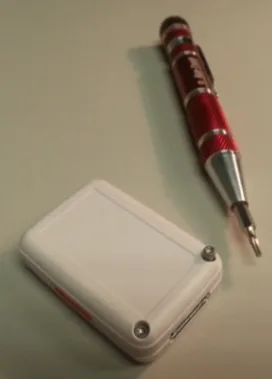
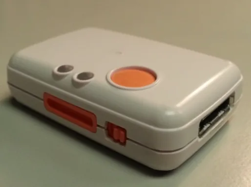
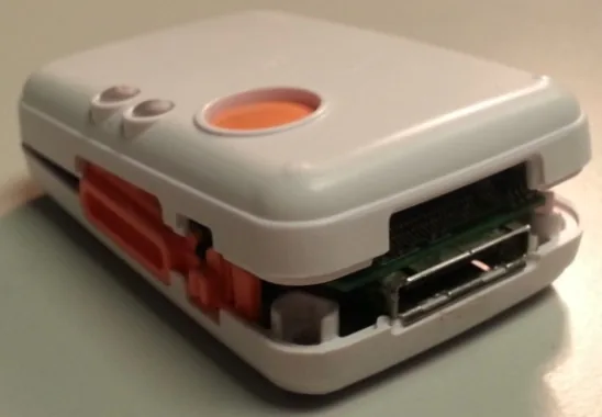
Figure 9‑1 Opening the enclosure
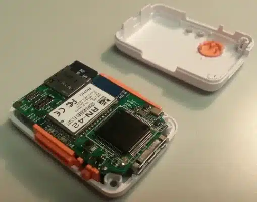
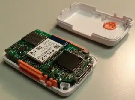
Figure 9‑2 Open enclosure with (left) and without (right) SD card
9.3.2. Assembling the enclosure
Ensure that you have all of the required plastic parts as shown in Figure 9‑3, as well as two screws (M2.0 x 8mm).
Assemble the orange clip fittings in the bottom of the enclosure (these are both the same so it doesn’t matter which one goes to which side).
Install the power switch cap, as shown in Figure 9‑4.
Place the circuit board, with the battery attached to the underside, into the bottom of the enclosure, as shown in Figure 9‑5.
The bottom of the enclosure has a plastic divider to hold the battery in place; ensure that the battery is fitted beside this divider.
Ensure that the power switch actuator sits in the notch on the power switch cap and that the dock connector sits neatly into its slot.
Ensure that the battery wires are fully underneath the circuit board and not obstructing the screw positions.
The orange clip fittings are designed to hold the circuit board in place – it should be an exact fit.
Insert the SD card, as shown in Figure 9‑5.
Carefully attach the top of the case, starting from the end of the dock connector, as shown in Figure 9‑6. When the top is in place, gently push down on the top to snap closed.
- Do not force the top closed – if there is an obstruction, remove the top to clear the obstruction before trying again.
Tighten the screws in the underside of the enclosure.
Note: it is very important to hold the boss ends together while running in the screw. Do not let the screws draw the parts together as this could damage the enclosure.
Note: do not over-tighten the screws as they may damage the top of the enclosure; when the top of the screw is flush with the plastic, stop tightening.
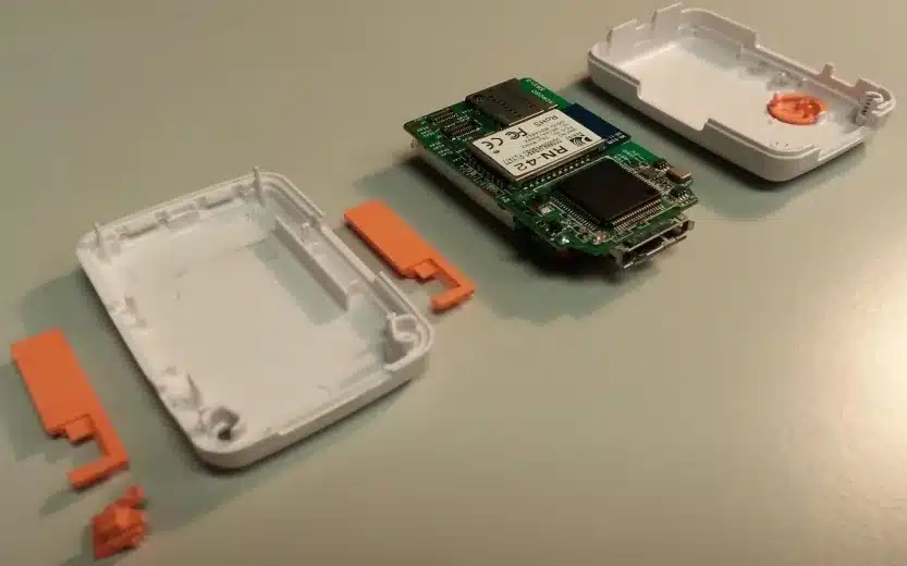
Figure 9‑3 Plastic enclosure parts
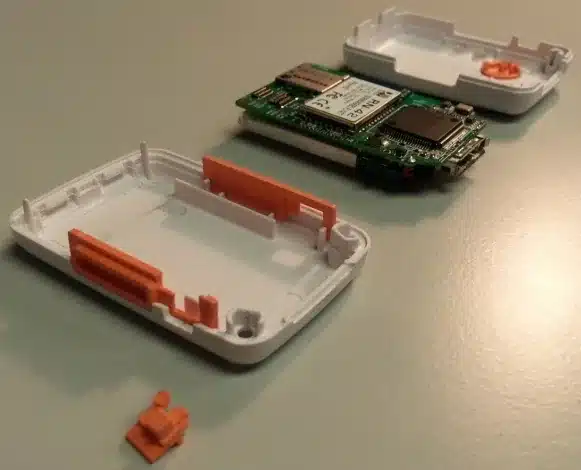
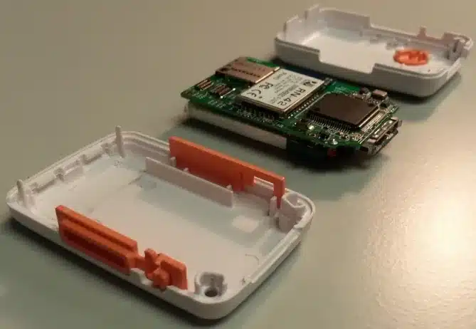
Figure 9‑4 Assembling clip fittings and power switch cap
Figure 9‑5 Installed circuit board and SD card insertion
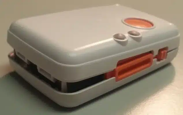
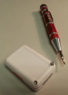
Figure 9‑6 Closing the enclosure and inserting screws
9.4. Appendix D – Shimmer3 sensor conflicts
The Shimmer3 sensors conflicts are shown below in Table 9‑1. Note that all Accelerometer, Magnetometer, Gyroscope, Pressure and Vbattery sensor channels are compatible with any other sensors.
| Int A14 | Int A1 | Int A12 | Int A13 | GSR | ExG1 24 Bit | ExG2 24 Bit | ExG1 16 Bit | ExG2 16 Bit | Br. Amp. | |
|---|---|---|---|---|---|---|---|---|---|---|
| Int A14 | – | OK | OK | OK | 🗶 | 🗶 | 🗶 | 🗶 | 🗶 | 🗶 |
| Int A1 | OK | – | OK | OK | 🗶 | 🗶 | 🗶 | 🗶 | 🗶 | OK |
| Int A12 | OK | OK | – | OK | OK | 🗶 | 🗶 | 🗶 | 🗶 | 🗶 |
| Int A13 | OK | OK | OK | – | OK | 🗶 | 🗶 | 🗶 | 🗶 | 🗶 |
| GSR | 🗶 | 🗶 | OK | OK | – | 🗶 | 🗶 | 🗶 | 🗶 | 🗶 |
| ExG1 24 Bit | 🗶 | 🗶 | 🗶 | 🗶 | 🗶 | – | OK | 🗶 | OK* | 🗶 |
| ExG2 24 Bit | 🗶 | 🗶 | 🗶 | 🗶 | 🗶 | OK | – | OK* | 🗶 | 🗶 |
| ExG1 16 Bit | 🗶 | 🗶 | 🗶 | 🗶 | 🗶 | 🗶 | OK* | – | OK | 🗶 |
| ExG2 16 Bit | 🗶 | 🗶 | 🗶 | 🗶 | 🗶 | OK* | 🗶 | OK | – | 🗶 |
| Br. Amp. | 🗶 | OK | 🗶 | 🗶 | 🗶 | 🗶 | 🗶 | 🗶 | 🗶 | – |
Table 9‑1 Shimmer3 sensor conflicts * Combining one ExG 24-bit channel with one ExG 16-bit channel causes no conflict in the firmware, but no Shimmer software application supports it.
The Shimmer3R sensor conflicts are shown below in Table 9‑1R. As on Shimmer3, all accelerometer (including the high-g accelerometer), magnetometer, gyroscope, pressure and battery voltage channels are compatible with any other sensors.
| Int A2 | Int A3 | Int A0 | Int A1 | GSR | ExG1 24 Bit | ExG2 24 Bit | ExG1 16 Bit | ExG2 16 Bit | Br. Amp. | |
|---|---|---|---|---|---|---|---|---|---|---|
| Int A2 | – | OK | OK | OK | 🗶 | 🗶 | 🗶 | 🗶 | 🗶 | 🗶 |
| Int A3 | OK | – | OK | OK | 🗶 | 🗶 | 🗶 | 🗶 | 🗶 | OK |
| Int A0 | OK | OK | – | OK | OK | 🗶 | 🗶 | 🗶 | 🗶 | 🗶 |
| Int A1 | OK | OK | OK | – | OK | 🗶 | 🗶 | 🗶 | 🗶 | 🗶 |
| GSR | 🗶 | 🗶 | OK | OK | – | 🗶 | 🗶 | 🗶 | 🗶 | 🗶 |
| ExG1 24 Bit | 🗶 | 🗶 | 🗶 | 🗶 | 🗶 | – | OK | 🗶 | OK* | 🗶 |
| ExG2 24 Bit | 🗶 | 🗶 | 🗶 | 🗶 | 🗶 | OK | – | OK* | 🗶 | 🗶 |
| ExG1 16 Bit | 🗶 | 🗶 | 🗶 | 🗶 | 🗶 | 🗶 | OK* | – | OK | 🗶 |
| ExG2 16 Bit | 🗶 | 🗶 | 🗶 | 🗶 | 🗶 | OK* | 🗶 | OK | – | 🗶 |
| Br. Amp. | 🗶 | OK | 🗶 | 🗶 | 🗶 | 🗶 | 🗶 | 🗶 | 🗶 | – |
Table 9‑1R Shimmer3R sensor conflicts * Combining one ExG 24-bit channel with one ExG 16-bit channel causes no conflict in the firmware, but no Shimmer software application supports it.
No conflict differs from Shimmer3: each row is Table 9‑1 with the channels renamed (Int A14 → Int A2, Int A1 → Int A3, Int A12 → Int A0, Int A13 → Int A1; see Analogue channel names), so GSR shares Int A3 where on Shimmer3 it shares Int A1.
9.5. Appendix E – Example configuration file (sdlog.cfg)
Shimmer3
accel=1
gyro=1
mag=1
exg1_24bit=0
exg2_24bit=0
gsr=0
extch7=0
extch6=0
br_amp=0
vbat=1
accel_d=0
extch15=0
intch1=0
intch12=0
intch13=0
intch14=0
accel_mpu=0
mag_mpu=0
exg1_16bit=0
exg2_16bit=0
pres=0
sample_rate=51.20
mg_internal_rate=6
mg_range=1
acc_internal_rate=0
accel_alt_range=0
pres_bmp180_prec=0
gsr_range=4
exp_power=0
gyro_range=1
gyro_samplingrate=155
acc_range=0
acc_lpm=0
acc_hrm=1
user_button_enable=1
rtc_error_enable=1
sd_error_enable=1
iammaster=0
sync=0
low_battery_autostop=0
interval=0
myid=0
Nshimmer=0
shimmername=Shimmer_9507
experimentid=DefaultTrial
configtime=1495542804
derived_channels=0
max_exp_len=0
EXG_ADS1292R_1_CONFIG1=0
EXG_ADS1292R_1_CONFIG2=128
EXG_ADS1292R_1_LOFF=16
EXG_ADS1292R_1_CH1SET=0
EXG_ADS1292R_1_CH2SET=0
EXG_ADS1292R_1_RLD_SENS=0
EXG_ADS1292R_1_LOFF_SENS=0
EXG_ADS1292R_1_LOFF_STAT=0
EXG_ADS1292R_1_RESP1=2
EXG_ADS1292R_1_RESP2=1
EXG_ADS1292R_2_CONFIG1=0
EXG_ADS1292R_2_CONFIG2=128
EXG_ADS1292R_2_LOFF=16
EXG_ADS1292R_2_CH1SET=0
EXG_ADS1292R_2_CH2SET=0
EXG_ADS1292R_2_RLD_SENS=0
EXG_ADS1292R_2_LOFF_SENS=0
EXG_ADS1292R_2_LOFF_STAT=0
EXG_ADS1292R_2_RESP1=2
EXG_ADS1292R_2_RESP2=1
Shimmer3R
This is the file a Shimmer3R writes for its factory default configuration, with a BMP390 pressure sensor. A Shimmer3R with a BMP581 writes pres_bmp581_prec in place of pres_bmp390_prec. The XXXX in shimmername is the last four characters of the Shimmer’s Bluetooth address.
accel=1
gyro=1
mag=1
exg1_24bit=0
exg2_24bit=0
gsr=0
extch0=0
extch1=0
br_amp=0
vbat=1
accel_d=0
extch2=0
intch3=0
intch0=0
intch1=0
intch2=0
accel_alt=0
mag_alt=0
exg1_16bit=0
exg2_16bit=0
pres=0
sample_rate=51.20
mg_internal_rate=3
mag_alt_range=0
acc_internal_rate=5
accel_ln_range=0
pres_bmp390_prec=0
gsr_range=4
exp_power=0
gyro_range=2
gyro_samplingrate=5
acc_range=0
acc_lpm=0
acc_hrm=1
mag_alt_rate=62
accel_alt_rate=0
user_button_enable=1
rtc_error_enable=1
sd_error_enable=1
iammaster=0
sync=0
low_battery_autostop=0
interval=54
bluetoothDisabled=0
max_exp_len=0
est_exp_len=1
myid=0
Nshimmer=0
shimmername=Shimmer_XXXX
experimentid=DefaultTrial
configtime=0
derived_channels=0
EXG_ADS1292R_1_CONFIG1=2
EXG_ADS1292R_1_CONFIG2=128
EXG_ADS1292R_1_LOFF=16
EXG_ADS1292R_1_CH1SET=0
EXG_ADS1292R_1_CH2SET=0
EXG_ADS1292R_1_RLD_SENS=0
EXG_ADS1292R_1_LOFF_SENS=0
EXG_ADS1292R_1_LOFF_STAT=0
EXG_ADS1292R_1_RESP1=0
EXG_ADS1292R_1_RESP2=2
EXG_ADS1292R_2_CONFIG1=2
EXG_ADS1292R_2_CONFIG2=128
EXG_ADS1292R_2_LOFF=16
EXG_ADS1292R_2_CH1SET=0
EXG_ADS1292R_2_CH2SET=0
EXG_ADS1292R_2_RLD_SENS=0
EXG_ADS1292R_2_LOFF_SENS=0
EXG_ADS1292R_2_LOFF_STAT=0
EXG_ADS1292R_2_RESP1=0
EXG_ADS1292R_2_RESP2=2
When SD sync is configured, the file also contains one node= line per node and, when a centre address is set, a center= line. These lines come after est_exp_len. On a board whose ADS1292R clock lines are tied, the firmware forces bit 3 of chip 1’s CONFIG2 on, so that line reads EXG_ADS1292R_1_CONFIG2=136 rather than 128.
Glossary
| ACLK | Auxiliary Clock |
|---|---|
| ADC | Analogue-to-Digital Converter |
| BSL | Boot Strap Loader |
| BT | Bluetooth |
| CPU | Central Processing Unit |
| CSMA | Carrier Sense Multiple Access |
| CVS | Concurrent Versioning System |
| DCO | Digitally Controlled Oscillator |
| DMA | Direct Memory Access |
| ECG | Electrocardiogram |
| ECG | Electrocardiogram |
| EEG | Electroencephalogram |
| EMG | Electromyogram |
| EOG | Electrooculography |
| FHSS | Frequency Hopping Spread Spectrum |
| GPIO | General Purpose Input/Output |
| GSR | Galvanic Skin Response |
| GUI | Graphical User Interface |
| HTML | Hypertext Markup Language |
| HTTP | Hypertext Transfer Protocol |
| ID | Instrument Driver |
| IEEE | Institute of Electrical and Electronic Engineers |
| ISM | Industrial, Scientific and Medical Band |
| LCD | Liquid Crystal Display |
| LED | Light Emitting Diode |
| MAB | Memory Address Bus |
| MAC | Media Access Control |
| MCLK | Master Clock |
| MDB | Memory Data Bus |
| MPR | Microprocessor and Radio Boards |
| MSS | Multi-Shimmer Sync |
| MTS | Mote Sensor |
| nesC | network embedded system C |
| PAN | Personal Area Network |
| PWM | Pulse Width Modulation |
| RAM | Random Access Memory |
| RF | Radio Frequency |
| RISC | Reduced Instruction Set Computer |
| ROM | Read Only Memory |
| RPM | RedHat Package Manager |
| SD | Secure Digital |
| SDK | Software Development Kit |
| SIG | Special Interest Group |
| SIMO | Slave In, Master Out |
| SIP | Session Initiation Protocol |
| SMCLK | Sub-Main Clock |
| SOMI | Slave Out, Master In |
| SPI | Serial Peripheral Interface |
| SPP | Serial Port Profile |
| STE | Slave Transmit Enable |
| TCP/IP | Transmission Control Protocol / Internet Protocol |
| UART | Universal Asynchronous Receiver/Transmitter |
| UCLK | USART Clock |
| USART | Universal Serial Asynchronous Receiver/Transmitter |
| USB | Universal Serial Bus |
| WBSN | Wireless Based Sensor Network |
| WSN | Wireless Sensor Network |
Since September 2014, all expansion modules sold by Shimmer are permanently fixed to the Shimmer3 mainboard. Removal of the expansion board from the mainboard should not be carried out under any circumstances. Doing so will cause damage to one or both of the boards and any necessary repairs will not be covered by warranty.↩︎
http://www.shimmersensing.com/support/wireless-sensor-networks-documentation/category/12↩︎
Note that using a value other than the Configuration ID automatically generated by Shimmer software applications will likely cause some confusion if the logged data is subsequently imported into Shimmer software, like Consensys, which assume that the value is related to the configuration date and time.↩︎
Legal Notices and Disclaimers · Intended Use and Safety · Agency Compliance · Welcome Message
Legal Notices and Disclaimers
Disclaimers
SHIMMER RESEARCH LTD. MAKES NO WARRANTY OF ANY KIND WITH REGARD TO THIS MATERIAL, INCLUDING, BUT NOT LIMITED TO, THE IMPLIED WARRANTIES OF MERCHANTABILITY AND FITNESS FOR A PARTICULAR PURPOSE. SHIMMER RESEARCH LTD. ASSUMES NO RESPONSIBILITY FOR ANY ERRORS THAT MAY APPEAR IN THIS DOCUMENT. SHIMMER RESEARCH LTD. MAKES NO COMMITMENT TO UPDATE NOR TO KEEP CURRENT THE INFORMATION CONTAINED IN THIS DOCUMENT.
THIS SPECIFICATION IS COPYRIGHTED BY AND SHALL REMAIN THE PROPERTY OF SHIMMER RESEARCH LTD. NO LICENSE, EXPRESS OR IMPLIED, BY ESTOPPEL OR OTHERWISE TO ANY INTELLECTUAL PROPERTY RIGHTS IS GRANTED HEREIN.
SHIMMER RESEARCH LTD. DISCLAIMS ALL LIABILITY, INCLUDING LIABILITY FOR INFRINGEMENT OF ANY PROPRIETARY RIGHTS, RELATING TO USE OF THE MATERIALS AND IMPLEMENTATION OF INFORMATION IN THIS SPECIFICATION. SHIMMER RESEARCH LTD. DOES NOT WARRANT OR REPRESENT THAT SUCH USE OR IMPLEMENTATIONS WILL NOT INFRINGE SUCH RIGHTS.
Redistribution IS permitted provided that the following conditions are met:
Redistributions must retain the copyright notice, and the following disclaimer. Redistributions in electronic form must reproduce the above copyright notice, this list of conditions and the following disclaimer in the documentation and/or other materials provided with the document.
Neither the name of Shimmer Research Ltd. nor the names of its contributors may be used to endorse or promote products derived from this document without specific prior written permission.
SHIMMER RESEARCH LTD. RETAINS THE RIGHT TO MAKE CHANGES TO THESE SPECIFICATIONS AT ANY TIME, WITHOUT NOTICE.
CAUTION
RISK OF EXPLOSION IF BATTERY IS REPLACED BY AN INCORRECT TYPE.
DISPOSE OF USED BATTERIES ACCORDING TO THE INSTRUCTIONS.
Legal Notices
Shimmer Research Ltd. software products are copyrighted by and shall remain the property of Shimmer Research Ltd. Use, duplication or disclosure is subject to restrictions stated in the three clause BSD license, or in the case of software delivered to the government, in accordance with the software license agreement as defined in FAR 52.227-7013.The Shimmer logo is a registered trademark of Shimmer Research Ltd.

Other brands, marks and names mentioned herein may be the property of their respective owners and used in accordance with published guidelines.
© SHIMMER RESEARCH LTD., All Rights Reserved
Intended Use and Safety
Shimmer is an open flexible platform intended for qualified personal conducting research in wearable sensor applications. Consequently, although great care was taken in the design of this device, there is some inherent risk both with the design and manufacturing that you assume when the device is in close proximity to your body or the body of your test subjects. Depending on local regulations, Shimmer may not fully comply with commercial product testing standards. Shimmer as sold lacks medical certifications (e.g. ANSI/AAMI/IEC). Shimmer devices should never be used for diagnostic purposes without full consideration of operator and subject risk. The following list describes some of the subject risks:
There is a risk of electrical shock due to manufacturing defects or improper use (see usage guidelines and warnings).
There is also a risk of sustaining a burn due to a catastrophic failure of the device which could result from overheating of components.
There is a risk of radio interference with the operation of other electronic devices and we make no claims to the consequences of this.
There is a risk of some minor skin irritation from electrode pads over prolonged periods of time which may cause discomfort.
The ExG and GSR+ electrode inputs have transient voltage suppression (TVS) intended to protect the device during defibrillation (it survives a shock; repeated shocks are not covered). This protection is not certified, and the device is not a medical device, so remove the electrodes before defibrillation is attempted.
Data privacy limitations: It should be understood from the outset and you should communicate to test subjects that the physiological data that is streamed, stored, and analyzed through use of the device is not anonymized or privacy-protected in any way and you should take appropriate precautions in the protection and handling of such data in your research activities. Shimmer itself may buffer raw physiological data unencrypted on the integrated flash memory device. RF data streaming from the Shimmer may not be encrypted and could be intercepted by others. RF data downstream from an aggregation device, such as a cell phone may not be encrypted and is likewise susceptible to access.
Physiological data generated through use of Shimmer may indicate conditions that your test subject was previously unaware of prior to participation in research using the device.
There may be a risk of exposure to minute amounts of chemicals from the manufacturing process or the components themselves (such as latex, lead etc.).
There may be an increased risk of physical injury by the physical presence of the device on a test subject’s body and you fully assume this responsibility.
Shimmer Research Ltd. is not liable for damage or loss of data when using the Shimmer platform.
Some Shimmer peripherals rely on 3rd party driver support. Whilst Shimmer Research has tested features using a typical system, in some cases the end user will need to contact the peripheral vendor for resolution of installation, compatibility or operational issues.
By your use of Shimmer you acknowledge these and other risks inherent in the use of an experimental device and you assume full responsibility for testing this device with human subjects.
Shimmer3 and Shimmer3R are not medical devices, and are not intended for the diagnosis, treatment or monitoring of any medical condition.
Agency Compliance
Shimmer3 and Shimmer3R use only pre-certified Bluetooth modules. The radio certifications are the module manufacturers’ (modular approval), and the Shimmer’s label gives the identifiers of the module it contains:
| Module | Fitted in | FCC ID | IC (ISED) |
|---|---|---|---|
| Roving Networks (Microchip) RN-42 | Shimmer3 | T9J-RN42 | 6514A-RN42 |
| Microchip RN4678 | Later Shimmer3 units | A8TBM78ABCDEFGH | 12246A-BM78SPPS5M2 |
| Ezurio Vela IF820 | Shimmer3R | SQG-VELAIF820 | 3147A-VELAIF820 (see Shimmer3R below) |
The module manufacturers also hold the module’s approvals for other countries and regions, such as the EU, the UK, Japan and Korea. Their listings give each approval number and the labelling it requires: the RN4678 worldwide regulatory compliance listing, and the certifications on the Vela IF820 support page.
FCC
The FCC ID marking label is attached to the back of the Shimmer and is to remain attached at all times to comply with FCC requirements for modular approval.
Here is an example of the text on the FCC ID marking label of a Shimmer3 with the RN-42:
Model: Shimmer 3
Contains: FCC : T9J-RN42
IC : 6514A-RN42
BT RADIO ID:
Made in Ireland

This device complies with Part 15 of the FCC Rules.
Operation is subject to the following two conditions:
(1) This device may not cause harmful interference, and
(2) This device must accept any interference received, including interference that may cause undesired operation.
RADIO AND TELEVISION INTERFERENCE
This equipment has been tested and found to comply with the limits for a Class B digital device, pursuant to Part 15 of the FCC rules. These limits are designed to provide reasonable protection against harmful interference in a residential installation. This equipment generates, uses, and can radiate radio frequency energy and, if not installed and used in accordance with the instructions, may cause harmful interference to radio communications. However, there is no guarantee that interference will not occur in a particular installation. If this equipment does cause harmful interference to radio or television reception, which can be determined by turning the equipment off and on, the user is encouraged to try to correct the interference by one or more of the following measures:
– Reorient or relocate the receiving antenna.
– Increase the separation between the equipment and the receiver.
– Connect the equipment into an outlet on a circuit different from that to which the receiver is connected.
– Consult the dealer or an experienced radio/TV technician for help.
Changes and Modifications not expressly approved by Shimmer Research Ltd. can void your authority to operate this equipment under Federal Communications Commission rules.
ICES-003 Label
Shimmer3R
Shimmer3R contains the Ezurio Vela IF820 Bluetooth module (Classic Bluetooth and Bluetooth Low Energy), part 453-00171C, with the module’s own integrated chip antenna. Its approvals are Ezurio’s:
| Region | Approval |
|---|---|
| USA (FCC) | FCC ID SQG-VELAIF820 (grantee Laird Connectivity LLC, now Ezurio; granted 6 October 2023). The label reads “Contains FCC ID: SQG-VELAIF820” |
| Canada (ISED) | IC 3147A-VELAIF820. The label reads “Contains IC: 3147A-VELAIF820”. The module complies with ICES-003 Issue 7 |
| EU and UK | Radio Equipment Directive 2014/53/EU and the UK Radio Equipment Regulations 2017, by Ezurio’s declarations of conformity; no regulatory ID is issued |
| Japan (MIC) | 201-230307 |
| Korea (KC) | R-C-L8C-VelaIF820 |
The FCC Part 15 statements above apply to Shimmer3R as well. Ezurio’s Vela IF820 Regulatory Information Guide gives the full conditions of each approval.
Welcome Message
Thank you for your purchase of Shimmer!
This User Manual will provide essential operating instructions and help you to understand the capabilities of the Shimmer3 platform. The latest version of this manual is also available for download from our website.
The manuals for every Shimmer product, the Consensys User Guide and the Troubleshooting and FAQs are on the documentation pages of the Shimmer website, always in their latest version. There are also tutorial videos on YouTube: search for ‘Shimmer Sensing’. If you have further questions, contact us through our contact page.
Best wishes,
The Shimmer Team
