
1. Introduction
This document is an accompaniment to the Shimmer3 ECG Unit (called ECG Unit in the rest of this document). Its purpose is to aid the user in getting started with ECG measurements.
The ECG Unit can be configured to measure electrical signals from the skin, including ECG (Electrocardiograph). Any user who wishes to use Shimmer hardware to record EMG (Electromyograph) signals from the skin should refer to the Shimmer3 EMG User Guide.
The five-wire, four-lead ECG Unit can be configured to record the pathway of electrical impulses through the heart muscle. This data can be recorded on resting and ambulatory subjects, or during exercise to provide information about the heart’s response to physical exertion. Signals are collected from the skin via five wires, which are connected externally to the ECG Unit, and to which should be attached conventional disposable electrodes. The ECG Unit uses a low-power, multichannel analog front-end especially designed for biopotential measurements, consisting of delta-sigma analog-to-digital converters and programmable gain amplifiers.
2. General Information
2.1. Safety Information
As a precaution it is important to note that the ECG leads are not to be applied to the subject’s body while unit is in a USB dock or multi-charger, or, for a Shimmer3R, connected to a USB-C cable.
The electrode inputs have transient voltage suppression (TVS) intended to protect the device during defibrillation (it survives a shock; repeated shocks are not covered), except the inputs named in Section 2.3. This protection is not certified, and the device is not a medical device, so remove the electrodes before defibrillation is attempted.
2.2. Pre-Requisites
- A Shimmer3 ECG Unit programmed with LogAndStream firmware, which streams data over Bluetooth and logs it to the SD card. Shimmer units are shipped with it, and Consensys installs updates.
Five DIN snap leads.
9-inch and 18-inch leads are shipped with the ECG Development Kit and ECG Bundles.
Replacements can be purchased from www.shimmersensing.com.
Surface ECG electrodes.
Disposable electrodes are shipped with the ECG Development Kit and ECG Bundles.
For replacements, see www.shimmersensing.com. Alternatively, the Covidien Kendall Disposable Surface EMG/ECG/EKG electrodes 1″ (24mm) or Covidien Kendall Disposable Surface EMG/ECG/EKG electrodes 1 3/8″ (35mm), available on www.bio-medical.com with product codes ‘BRD H124SG’ and ‘BRD H135SG’, respectively, and the Ambu Blue Sensor T electrodes, available from various suppliers, are all suitable options and have been validated for use with Shimmer equipment.
2.3. ECG Unit Specification Overview
- For specifications on the general Shimmer3 part (i.e. microprocessor, radio, data storage and inertial sensors) of the Shimmer3 ECG Unit, please refer to the Shimmer3/3R User Manual.
Shimmer3R: The Shimmer3R ECG Unit uses the same front end, two TI ADS1292R chips, so the gain, data rate, input range, bandwidth, driven ground, input protection and connections listed here apply to it too. The Shimmer3R ECG, EMG and Ebio are the same device, configured for each. It weighs 31 g and measures 65 × 32 × 12 mm. For the general part of a Shimmer3R (processor, radio, storage and kinematic sensors), see Shimmer3R hardware in the Shimmer3/3R User Manual.
Gain: Configurable (1, 2, 3, 4, 6, 8, 12)
Data rate: software configurable (125, 250, 500, 1000, 2000, 4000, 8000 SPS)
Input differential dynamic range1: approx 800 mV (for gain = 6).
Bandwidth2: 8.4 kHz
Ground: Wilson Type Driven Ground
Input Protection: ESD and RF/EMI filtering; Current limiting; inputs include defibrillation protection (survive only, not repeat). NOTE: For inputs LA and RA the defibrillation protection is not present in order to facilitate Respiration demodulation.
Connections: Input RA, Input LA, Input LL, Input Vx, Reference (RL)
- All Hospital-Grade 1mm Touchproof IEC/EN 60601-1 DIN42802 jacks.
Ultra-lightweight (31 grams); Compact Dimensions (65 x 32 x 12 mm).
EEPROM memory: 2048 bytes.
3. Using the ECG Unit
3.1. Basic System Overview
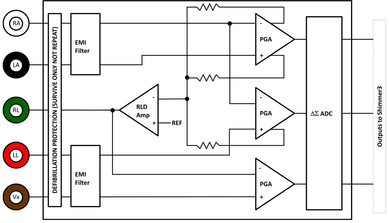
Figure 3‑1: Simplified Block Diagram
Electrodes: Each ECG board connects to RA (white), LA (black), RL (green), LL (red) and Vx (brown) electrodes.
Defibrillation protection: Survive only; not repeat. No defibrillation protection is present for inputs RA and LA to facilitate Respiration demodulation.
EMI Filter: Reduces electromagnetic interference; -3dB filter bandwidth is approximately 3MHz.
Right-Leg Drive Amplifier (RLD Amp): Counteracts common-mode interference (e.g. from mains power lines, fluorescent lights and other sources).
Programmable Gain Amplifier (PGA): Increases amplitude of input signal; seven gain settings available. See Section 4.5 to accurately calculate the gain of your device. Default gain is configurable in software.
∆Σ Analog to Digital Converters (∆Σ ADC): Converts the input analogue signals to a digital representation of this signal by a 24-bit signed integer value to each sample. These values are fed to the Shimmer3 processor to be saved to the SD card or transmitted over Bluetooth.
3.2. ECG Leads
In the context of electrocardiography, the word “lead” is used to refer to the signal of the voltage difference between two electrodes (i.e. the signal produced by the ECG recorder). In order to avoid any confusion, the wires that are used to physically connect the electrodes to the ECG Unit are referred to throughout this document as just that – “wires”.
The ECG Unit provides a four-lead ECG solution, with the following leads being measured in the recommended configuration:
Bipolar limb leads:
Lead I (LA-RA) is the ECG vector signal measured from the RA (right arm) position to the LA (left arm) position. This is output on the ExG1 Ch2 channel of the ECG Unit.
Lead II (LL-RA) is the ECG vector signal measured from the RA (right arm) position to the LL (left leg) position. This is output on the ExG1 Ch1 channel of the ECG Unit.
Lead III (LL-LA) is the ECG vector signal measured from the LA (left arm) position to the LL (left leg) position. This is derived by subtracting Lead I from Lead II.
Unipolar leads:
Electrode Positioning
The inputs to the ECG Unit are labelled according to the suggested placement, in order to measure the four channels listed above:
Bipolar limb lead electrodes:
LA Left Arm
RA Right Arm
LL Left Leg
RL Right Leg
Unipolar lead electrode positions:
- Vx V1, V2, V3, V4, V5 or V6, on the chest
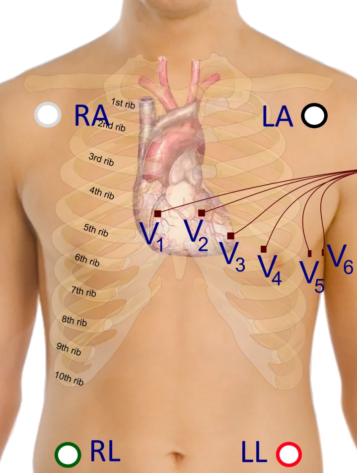
Figure 3‑2 Example positioning of the electrodes for ECG measurement with 18″ leads
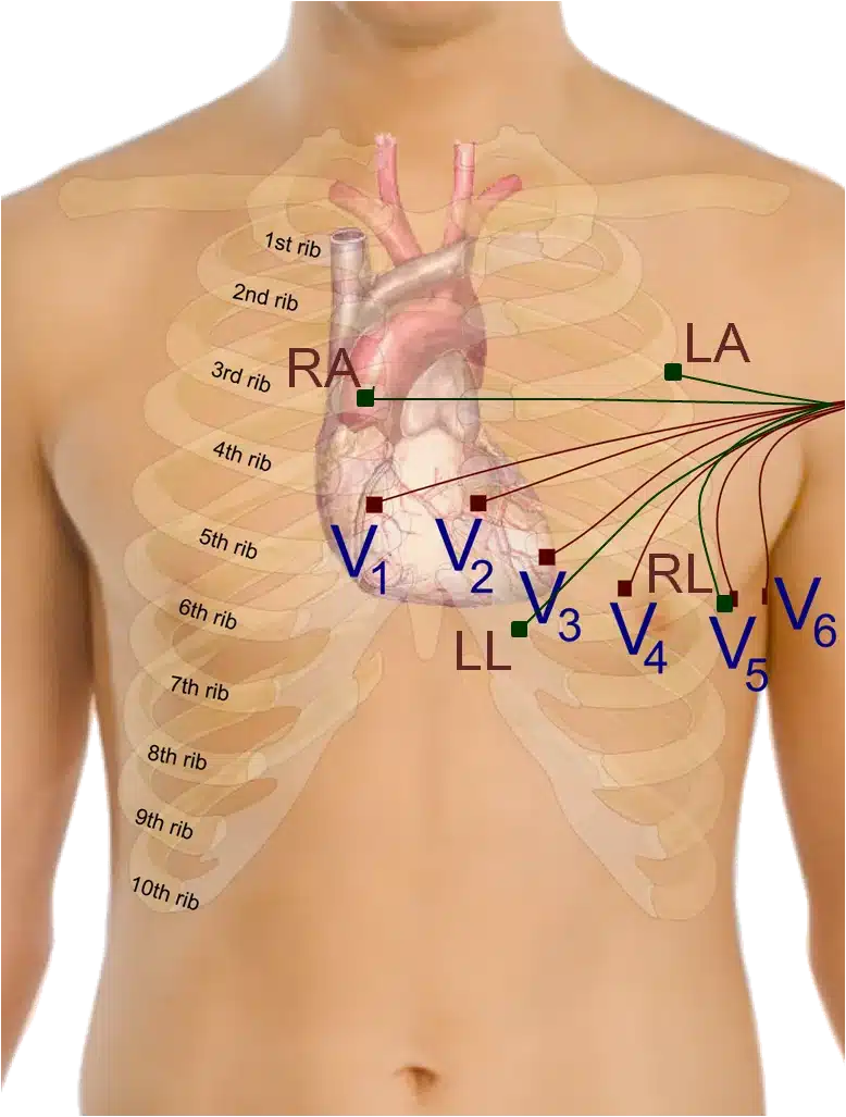
Figure 3‑3: Example positioning of the electrodes for ECG measurement with 9” leads
Figure 3‑2 shows an example of how the electrodes should be positioned on the body. The electrodes for the bipolar limb leads (LA, RA, LL and RL) are represented by green nodes and wires, whilst the V1, V2, V3, V4, V5 and V6 positions for the unipolar leads, are represented by brown nodes and wires.
Although it is common practise to place the limb electrodes on the arms/legs, according to their names, in reality, all of the limb electrodes can be placed on the chest. The important thing is that each electrode should be placed on the body, away from the heart and in the direction of the joint to the relevant limb. For example, the RA electrode can be placed anywhere on the chest as long as it is positioned away from the heart in the direction of the right shoulder, as shown in Figure 3‑3.
The reference electrode (RL) can be placed anywhere on the body as long as it is outside of the triangle formed by the 3 other limb electrodes (i.e. RA, LA and LL). In the diagram below it is placed at the V5 position, laterally on the left side of the torso. This position allows for the highest quality capturing of R waves. [1]
The Vx electrode can be placed at any of the positions, V1, V2, V3, V4, V5 or V6, depending on the user’s requirements.
Wilson’s Central Terminal
The Wilson’s Central Terminal (WCT) is a voltage that represents the average potential of the body and acts as a reference point, with respect to which the voltage difference for the unipolar leads is measured. It is calculated by averaging the voltage measured at the RA, LA and LL electrodes.
The inverted WCT voltage is driven to the body via the RL electrode to create a negative feedback loop in the measurement system and provide common mode interference rejection.
3.3. Configuration Options and Recommended Settings
The ECG Unit contains two ADS1292R chips from Texas Instruments; these have a very wide and varied range of available configuration options. These chips are referred to as “Chip1” and “Chip2” throughout this document. This section aims to provide recommended settings, which will suit the needs of most ECG measurement applications. The experienced user who wishes to have full control over all of the configuration settings should refer to the ADS1292R datasheet from Texas Instruments for more details.
There are two ADS1292R chips on the ECG Unit and each of these chips has eleven bytes of configurable register settings. Ten of these configurable bytes are listed in Table 3‑1 and their recommended values are discussed in this section. The final byte, which pertains to GPIO settings, is dealt with in firmware and not discussed here.
Byte |
Name |
Bit 7 |
Bit 6 |
Bit 5 |
Bit 4 |
Bit 3 |
Bit 2 |
Bit 1 |
Bit 0 |
|---|---|---|---|---|---|---|---|---|---|
0 |
CONFIG1: Configuration Register 1 |
0 |
0 |
0 |
0 |
0 |
Data Rate |
||
1 |
CONFIG2: Configuration Register 2 |
1 |
0 |
1 |
0 |
X 1 |
0 |
INT_TEST |
TEST_FREQ |
2 |
LOFF: Lead-Off Control Register |
0 |
0 |
0 |
1 |
0 |
0 |
0 |
0 |
3 |
CH1SET: Channel 1 Settings |
0 |
Gain1 |
MUX1 |
|||||
4 |
CH2SET: Channel 2 Settings |
0 |
Gain2 |
MUX2 (M2_3, M2_2, M2_1, M2_0) |
|||||
5 |
RLD_SENS: Right Leg Drive Sense Selection |
0 |
0 |
PDB_RLD |
RLD_LOFF_SENS |
RLD Settings (RLD2N, RLD2P, RLD1N, RLD1P) |
|||
6 |
LOFF_SENS: Lead-Off Sense Selection |
0 |
0 |
0 |
0 |
0 |
0 |
0 |
0 |
7 |
LOFF_STAT: Lead-Off Status Selection |
0 |
0 |
0 |
0 |
0 |
0 |
0 |
0 |
8 |
RESP1: Respiration Control Register 1 |
0 |
0 |
0 |
0 |
0 |
0 |
1 |
0 |
9 |
RESP2: Respiration Control Register 2 |
0 |
0 |
0 |
0 |
0 |
0 |
RLDREF_INT |
1 |
The Bit 3 in CONFIG2 denotes “X=0” for SR47-1 revision, and “X=1” for SR47-4 and greater revisions. This feature has been configured automatically in both LogAndStream 0.11.0 and SDLog_v0.19.0 (and newer).↩︎
Table 3‑1 lists the recommended values of the ADS1292R configuration register bytes. The values of the individual bits are listed in the columns labelled Bit 7 (MSB), Bit 6, and so on to Bit 0 (LSB). The recommended values of some sets of bits, like multiplexer (MUX) settings, channel gain settings and others, differ depending on the type of signal being measured (e.g. ECG or EMG), and others, like output data rate and test signal, depend on the user’s preferences.
Data Rate
The Data Rate for each chip can be set by modifying the three LSBs of the CONFIG1 register (Byte 0). Table 3‑2 lists the valid options and their corresponding data rate value in units of samples per second (SPS). For ECG, a data rate of 500 SPS or more is recommended, although the needs of a given application may vary.
| Data Rate (SPS) | DR2 | DR1 | DR0 |
|---|---|---|---|
| 125 | 0 | 0 | 0 |
| 250 | 0 | 0 | 1 |
| 500 (recommended) | 0 | 1 | 0 |
| 1000 | 0 | 1 | 1 |
| 2000 | 1 | 0 | 0 |
| 4000 | 1 | 0 | 1 |
| 8000 | 1 | 1 | 0 |
| DO NOT USE | 1 | 1 | 1 |
Table 3‑2 ECG Data Rate options
Gain
The Gain setting can be configured independently for each of the two data channels on each chip by modifying bits 4 – 6 of the CH1SET byte for channel 1 and of the CH2SET byte for channel 2, respectively. The gain bits for channel 1 of a given chip are listed as G1_2 (MSB), G1_1 and G1_0 (LSB) in Table 3‑1, whilst the equivalent for channel2 of the chip are listed as G2_2, G2_1 and G2_0, respectively. These are collectively referred to as Gx_2, Gx_1 and Gx_0, respectively, in Table 3‑3, which lists the valid options and the corresponding gain value for each. For ECG, a gain value of 4 is recommended.
| Gain | Gx_2 | Gx_1 | Gx_0 |
|---|---|---|---|
| 6 (default) | 0 | 0 | 0 |
| 1 | 0 | 0 | 1 |
| 2 | 0 | 1 | 0 |
| 3 | 0 | 1 | 1 |
| 4 (recommended) | 1 | 0 | 0 |
| 8 | 1 | 0 | 1 |
| 12 | 1 | 1 | 0 |
| DO NOT USE | 1 | 1 | 1 |
Table 3‑3 ECG Channel Gain options
Input Multiplexer
The multiplexer (MUX) settings can be configured independently for each of the two data channels on each chip; the MUX bits for channel 1 of a given chip are listed as MUX1_3 (MSB), MUX1_2, MUX1_1 and MUX1_0 (LSB) in Table 3‑1, whilst the equivalent for channel2 of the chip are listed as MUX2_3, MUX2_2, MUX2_1 and MUX2_0, respectively. Table 3‑4 lists the recommended MUX configuration for each chip and channel for ECG data collection.
| Chip | MUX1_3 | MUX1_2 | MUX1_1 | MUX1_0 | MUX2_3 | MUX2_2 | MUX2_1 | MUX2_0 |
|---|---|---|---|---|---|---|---|---|
| Chip1 | 0 | 0 | 0 | 0 | 0 | 0 | 0 | 0 |
| Chip2 | 0 | 0 | 0 | 0 | 0 | 1 | 1 | 1 |
Table 3‑4 Recommended MUX settings for ECG
Right-Leg Drive
The right-leg drive (RLD) settings determine the voltage that should be used at the input of the right-leg drive amplifier for common-mode interference rejection and can be configured independently for each chip. The RLD Settings bits for a given chip are listed as RLD2N, RLD2P, RLD1N and RLD1P in Table 3‑1. For ECG configuration, the recommended setting is to choose the Wilson’s Central Terminal voltage ((RA + LA + LL)/3) as the negative input to the RLD amplifier on Chip1 and no RLD signal on Chip2. This can be achieved by setting the configuration listed in Table 3‑5.
| Chip | RLD2N | RLD2P | RLD1N | RLD1P |
|---|---|---|---|---|
| Chip14 | 1 | 1 | 0 | 1 |
| Chip2 | 0 | 0 | 0 | 0 |
Table 3‑5 Recommended RLD channel selection settings for ECG – Wilson terminal voltage Table 3‑6 gives an alternative configuration in which, rather than using the Wilson terminal voltage, the voltage on the RLD electrode is held at a fixed potential – in this case half of the ExG chips’ 3.0 V analogue supply (approximately 1.5 V), on Shimmer3 and Shimmer3R.
| Chip | RLD2N | RLD2P | RLD1N | RLD1P |
|---|---|---|---|---|
| Chip1 | 0 | 0 | 0 | 0 |
| Chip2 | 0 | 0 | 0 | 0 |
Table 3‑6 Alternative RLD channel selection settings for ECG – fixed potential In Consensys these are the Reference Electrode options Inverse Wilson CT (Table 3‑5) and Fixed Potential (Table 3‑6).
The PDB_RLD bit of the RLD_SENS byte (byte 5, bit 5) determines if the RLD buffer is powered on (1) or not (0).
The RLD_LOFF_SENS bit of the RLD_SENS byte (byte 5, bit 4) determines if the lead-off sense function is enabled (1) or disabled (0).
The RLDREF_INT bit of the RESP2 byte (byte 9, bit 1) controls the RLDREF signal source for the RLD amplifier. If the value of the bit is 0, the reference signal is fed externally. If the value of the bit is 1, an internally generated reference signal is generated.
For ECG data collection, the settings in Table 3‑7 are recommended for PDB_RLD, RLD_LOFF_SENS and RLDREF_INT.
| Chip | PDB_RLD | RLD_LOFF_SENS | RLDREF_INT |
|---|---|---|---|
| Chip1 | 1 | 0 | 1 |
| Chip2 | 0 | 0 | 0 |
Table 3‑7 Recommended RLD settings for ECG
Test Signal
In order to test the ECG output channels, a test signal can be internally generated by each chip. This signal can either be a DC voltage or a 1Hz square wave. To enable the test signal, the two LSBs of the CONFIG2 byte (byte 1, bits 1-0) for each chip should be set as in Table 3‑8. Furthermore, the MUX1 or MUX2 bits should be set to 0000 so that the test signal will appear on channel 1 or channel 2, respectively.
| Test signal | INT_TEST | TEST_FREQ |
|---|---|---|
| DC test signal | 1 | 0 |
| 1 Hz square wave test signal | 1 | 1 |
| No test signal | 0 | 0 |
Table 3‑8 Test signal settings for ECG
Respiration demodulation
The ADS1292R includes circuitry for measuring respiration by impedance pneumography. Section 4.6 describes electrode placement, configuration and an example.
Lead-off detection configuration
The ADS1292R from Texas Instruments provides the ability to detect if an electrode has been disconnected from the body. This is implemented inside the chip by enabling a constant DC current source and sink on each pair of bipolar inputs. Once enabled, when one of the electrodes is disconnected from the body, the voltage at that electrode will be pulled high or low – this will be apparent on the measured voltage signal.
Note: due to the nature of the measurement method, by enabling lead-off detection the measurement system will be more susceptible to thermal noise and a small DC voltage offset is introduced into the ECG signal measurements.
Consensys makes these changes for you: set Lead-Off Detection to DC Current in its ECG/EMG settings, which also sets Lead-Off Current to 22 nA and Lead-Off Comparator Threshold to Pos:90% – Neg:10%, the levels recommended below. To configure the chips yourself, make the following changes to the recommended ECG configuration bytes.
Chip – Byte |
Mask (hex) |
Mode |
||
|---|---|---|---|---|
DC Current Byte Value (hex) |
Off Byte Value (hex) |
|||
Source |
Chip 1 – Byte 2 Chip 2 – Byte 2 |
0x01 |
0x00 (DC Current) |
N/A |
General comparators (Enable/disable) |
Chip 1 – Byte 1 Chip 2 – Byte 1 |
0x40 |
0x40 (On) |
0x00 (Off) |
Comparators on each input |
Chip 1 – Byte 6 |
0x0F |
0x07 (2P, 1N, 1P) |
0x00 (Off) |
Chip 2 – Byte 6 |
0x0F |
0x04 (2P) |
0x00 (Off) |
|
RLD sense |
Chip 1 – Byte 5 |
0x10 |
0x10 (On) |
0x00 (Off) |
The level of DC current used for lead-off detection can be set by changing configuration bytes as shown in Table 3‑10. From lab testing we have found 22nA to be a suitable level for lead-off detection.
| Chip 1 – Byte 2 and Chip 2 – Byte 2 | |||
|---|---|---|---|
| Current | Mask (hex) | Byte Value (hex) | Byte Value (dec) |
| 6nA | 0x0C | 0x00 | 0 |
| 22nA | 0x0C | 0x04 | 4 |
| 6uA | 0x0C | 0x08 | 8 |
| 22uA | 0x0C | 0x0C | 12 |
The ADS1292R has built-in voltage comparators that are connected to each of the electrode inputs and can be enabled or disabled in the configuration bytes – see Table 3‑9. The voltage threshold at which these comparators are triggered – given as a percentage of the supply voltage – can be configured as shown in Table 3‑11 below. From lab testing we have found a comparator threshold of “Pos:90% – Neg:10%” to be a suitable level for lead-off detection.
| Chip 1 – Byte 2 and Chip 2 – Byte 2 | |||
|---|---|---|---|
| Comparator threshold | Mask (hex) | Byte Value (hex) | Byte Value (dec) |
| Pos:95% – Neg:5% | 0xE0 | 0x00 | 0 |
| Pos:92.5% – Neg:7.5% | 0xE0 | 0x20 | 32 |
| Pos:90% – Neg:10% | 0xE0 | 0x40 | 64 |
| Pos:87.5% – Neg:12.5% | 0xE0 | 0x60 | 96 |
| Pos:85% – Neg:15% | 0xE0 | 0x80 | 128 |
| Pos:80% – Neg:20% | 0xE0 | 0xA0 | 160 |
| Pos:75% – Neg:25% | 0xE0 | 0xC0 | 192 |
| Pos:70% – Neg:30% | 0xE0 | 0xE0 | 224 |
The outputs of the voltage comparators are stored in the status byte channel from each chip where a ‘0’ represents a connected electrode and a ‘1’ indicates a disconnected electrode. In each chip’s status byte, bit 0 is input 1P, bit 1 is 1N, bit 2 is 2P, bit 3 is 2N and bit 4 is the right-leg drive (RLD); bit 7 is always 1. In Consensys exports, the status bytes are the ECG_EMG_Status1 and ECG_EMG_Status2 columns.
| ECG electrode | Chip input | Lead-Off Status Byte |
|---|---|---|
| LA | Chip 1 – 2P | Chip 1 – Bit2 |
| RA | Chip 1 – 1N | Chip 1 – Bit1 |
| LL | Chip 1 – 1P | Chip 1 – Bit0 |
| Vx | Chip 2 – 2P | Chip 2 – Bit2 |
| RLD | Chip 1 – RL | Chip 1 – Bit4 |
Table 3‑12 The relevant bits in each of the status bytes that represent the lead-off status of each of the electrodes for ECG mode
4. Measuring ECG Signals
4.1. Best Practice on How to Acquire a High Quality ECG signal
Skin Preparation
Skin preparation is not essential for ECG measurements; however, ensuring a good electrode to skin contact improves signal quality and minimises the likelihood of signal interference from electrodes falling off or sporadic contact caused by hairs or dirt particles. As such, if an improved signal quality is required, any hairs at the contact point can be shaved off and the skin should be cleaned with alcohol or sanitizer to remove oils and sweat which can interfere with the signal [2].
Sampling Frequency
Although the choice of sampling frequency is entirely up to the user, a sampling rate of 512Hz is recommended for clinical grade ECG data acquisition. Lower rates can be used for ambulatory ECG measurements [3].
Wires
Because ECG signals have a very low voltage, it is recommended that the minimum feasible wire length is used to minimise signal interference. Simply put, the shorter the wire, the less interference will be experienced in the signal. Interference can come from motion artifact, mains interference (50/60Hz) and other wireless signals and becomes much more significant with longer wires. Should you require longer wires for your application, it is likely you will require mains notch filtering (as described below).
Wires can also be secured to reduce noise from motion artefact and eliminate the possibility of them pulling on electrodes which can cause them to fall off and reduce electrode to skin contact quality.
Filtering
Mains Notch Filtering
If your signal is experiencing interference from mains electricity, a software band-stop filter should be applied. Eliminate the 50Hz frequency in most parts of the world or 60Hz frequency in the Americas. The APIs and Instrument Drivers, provided by Shimmer for development of software in Java/Android, LabVIEW, Matlab and C#, include the implementation of optional mains filtering in the example code.
High Pass Filtering
In order to eliminate low frequency components of the signal, high pass filtering is recommended. A cut-off frequency of 0.05 Hz is recommended for diagnostic ECG, whilst a cut-off frequency of 0.5 Hz is suitable for longer term ECG monitoring. Care should be taken in the design of filters and it should be remembered that the filters may impose the requirement for a settling time after data collection starts. The APIs and Instrument Drivers, provided by Shimmer for development of software in Java/Android, LabVIEW, Matlab and C#, include the implementation of optional high pass filtering in the example code.
4.2. Basic ECG Waveform Features
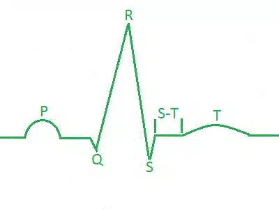
Figure 4‑1: ECG Waveform of one heart beat.
Baseline: No overall depolarization or repolarization.
P Wave: Atrial depolarization.
Duration = 80-100ms.
- PR Segment: AV nodal delay.
Duration = 120-200ms.
- QRS Complex: Ventricular depolarization (atria repolarizing simultaneously).
Duration = 80-120ms.
- ST Segment: Time during which ventricles are contracting and emptying.
Duration =70-80ms.
T Wave: Ventricular repolarization. Duration ≈200ms.
TP Interval: Time during which the ventricles are relaxing and filling. [4]
4.3. How to Determine the Heart Rate from ECG
It is a simple process to calculate heart rate (HR) in beats per minute (BPM) from the electrocardiogram using the R waves (which are part of the QRS complex described above). Shimmer’s proprietary software, ConsensysPRO implements an ECG-to-HR algorithm to give users’ access to HR from their Shimmer ECG, see Figure 4‑2 for reference.
First, make a note of the sampling rate in Hz (Fs) of the signal. Then, note the sample number of the first R wave detected (S1) and the sample number of the last R wave detected (S2). Count the total number R waves (NR) between S1 and S2, including the waves at both S1 and S2.
The HR in BMP is then given by the following equation:
HR (BPM) = 60*( NR –1)/(( S2– S1)/ Fs)
Example HR Calculation
Figure 4‑2 shows an example ECG signal with two distinct R waves and the following parameters:
NR = 2, S2 = 843, S1 = 331, Fs = 512 Hz.
HR = 60*(2-1)/((843-331)/512) = 60 BPM.
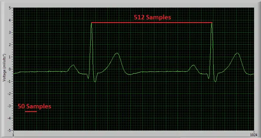
Figure 4‑2: Diagram of ECG signal captured with ‘Multi-Shimmer Sync’ for HR calculation example.
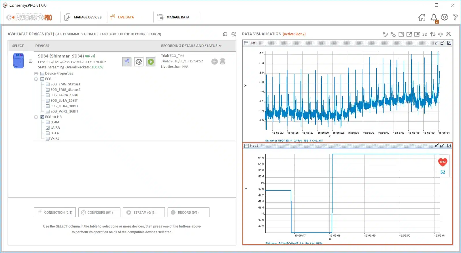
Figure 4‑3: Diagram of ECG signal and derived HR signal using ConsensysPRO software
Overview of Popular QRS Detection Methods
The following are examples of some of the most commonly used QRS detection algorithms. QRS detection algorithms are the foundation of ECG signal analysis and can be used to estimate heart rate, as shown above, among many other things. QRS detection algorithms started being developed about 40 years ago and now come in many forms. Those outlined below are intended to aid the user in getting started with investigating the topic and to direct them towards some of the appropriate literature on the subject.
Köhler et al. completed a comprehensive overview of many different techniques of software QRS detection; their paper serves as a good introduction to the subject matter [5].
Please note that free software solutions for QRS detection analysis are not currently provided by Shimmer and the information below is intended as a starting point for the new user to aid their software development. Should you require a ‘pre-packed’ software solution, please contact the Shimmer team to discuss it further.
- The Pan-Tompkins Algorithm [6]
This is the most widely known real-time QRS detection algorithm. The method combines filtering, differentiator, squaring and integrator processes to detect each QRS complex. The method was developed in 1985 and is very reliable; it is no longer the state-of-the art in QRS detection but is suitable for many applications. M. Lascu and D. Lascu have published a very useful paper about implementing the algorithm in LabVIEW [7]. Portet et al. [8], among others [2, 6], have comparatively evaluated the algorithm.
- Wavelet Analysis Algorithms
Wavelet Analysis Algorithms are an increasingly popular option for QRS detection. There are multiple methods involving wavelet analysis, e.g. a multi-stage method which has shown higher sensitivity (99.93%) than the Pan-Tompkins algorithm (99.75%) [9] and the method used by Zidelmal et al. [10] involving wavelet coefficient analysis which has shown an increased positive predictivity (99.82%) in comparison to the Pan-Tompkins algorithm (99.54%). There can be advantages to wavelet analysis algorithms but they are more complex and less widely documented than the Pan-Tompkins algorithm so may require more time and expertise to implement.
- Cross-Correlation Algorithms
Cross-correlation (C-C) algorithms and multi-stage cross-correlation methods are also popular QRS detection techniques. Multi-stage C-C algorithms are particularly useful for applications where the P and T waves (see Figure 4‑1) are required to be detected in addition to the QRS complex. Last et al. [11] showed that, by including templates for each wave component, it is possible to record precise timings of each stage of the cardiac cycle. In summary, cross-correlation algorithms, in particular, multi-component based ones, allow for a high level of detail in analysis but require more computing power than simple algorithms like Pan-Tompkins and are not always suitable for real-time analysis.
- Others
Many other approaches exist in order to detect the QRS complex. These can be found by a literature search with keywords, such as ‘Neural Network Approaches’, ‘Adaptive Filters’, ‘Hidden Markov Models’, ‘Mathematical Morphology’, ‘Hilbert Transform based QRS detection’ and ‘Length and Energy Transforms’. Before selecting the methodology you wish to use, it is highly recommended that you consider the accuracy your data requires and the amount of computer processing you can facilitate.
4.4. Aliasing Error and Sampling Rate
At low sampling rates, ECG signal quality is significantly reduced. One effect of this is R wave height variation. Figure 4‑4, Figure 4‑5 and Figure 4‑6 below show a 30 BPM ECG recording at 102.4Hz, a 60 BPM recording at 204.8Hz and an 120 BPM recording at 512Hz respectively. It is noticeable that the variation in R wave height variation is minimised with increased sampling frequency. Whilst the 512Hz sampling rate allows for clinical grade signal recordings it may not be necessary for your application. If a lower sampling rate is used less data is stored saving memory space and computer usage, a higher sampling rate provides a much better replication of the real ECG signal but increases computer usage and memory used.
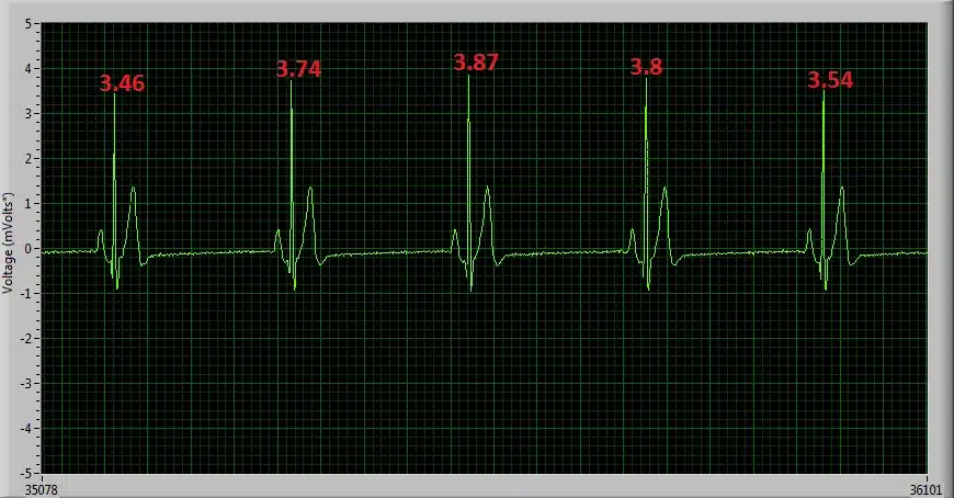
Figure 4‑4: 30 BPM ECG signal sampled at 102.4Hz, showing high R wave height variation.
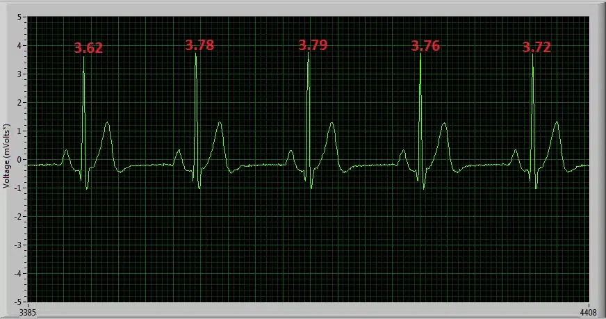
Figure 4‑5: 60 BPM ECG signal sampled at 204.8Hz, showing reduced R wave height variation.
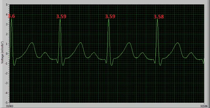
Figure 4‑6: 120 BPM ECG signal sampled at 512Hz, showing minimal R wave height variation.
4.5. Signal Calibration
The ADC output for each channel from the ECG Unit has a signed 24bit digital format. The relationship between the ADC output and the ECG Signal in mVolts is given by the formula:
Equation 1
In order to convert the ADC output signal to mVolts which is the standard unit for an ECG signal, the above formula can be rearranged as follows:
, Equation 2
where
. Equation 3
Considering that the ADC sensitivity is known and that the ADC Output is measured from the Shimmer, in order to calculate the ECG signal in mVolts, the values for the Gain and ADC Offset must simply be inserted into Equation 2.
The nominal value for the ADC offset of the ECG Unit data channels is 0 and the gain is software configurable (see Section 3.3). For most applications these values are sufficiently accurate. If improved accuracy is required for a given application, then the gain and ADC Offset of each of the ECG Unit channels can be measured.
ADC Offset Measurement
To determine the offset of each channel, the relevant inputs for that channel should be connected to each other. For example to determine the Lead II offset, the RA and LL inputs should be connected to each other. The ADC offset for the Lead II channel is then calculated as the mean ADC output on the ECG LL-RA channel of the Shimmer with the RA and LL inputs connected together. This can easily be found by saving uncalibrated data to a file and then calculating the mean value. The offset for other channels is calculated similarly.
Gain Measurement
In order to determine the gain for the ECG sensor channels, a sine wave signal from a signal generator should be applied to the sensor electrodes. The channels should be calibrated separately, with the sine wave signal applied to the appropriate pair of electrodes in each case. It is recommended to use a signal with amplitude ±1 mV approx (2 mV peak-to-peak) and frequency between 0.05Hz and 159Hz. The gain for each channel may differ.
The gain for each channel is calculated as follows
Equation 4
where the ADC Offset and ADC Sensitivity are as defined previously, Max ADC Output is the maximum value of the uncalibrated data on the channel of interest and Max Input Signal in mVolts is the half wave amplitude of the input sine-wave signal (e.g. 1mV when using a signal of ±1 mV).
4.6. Measuring Respiration
The Shimmer3 ECG unit can be configured to measure respiration. This section gives recommendations regarding electrode placement, configuration settings for respiration detection, as well as an illustration of the signals that can be achieved from the device before and after post‑processing.
The respiration detection method used, is called “impedance pneumography”. The Shimmer3 ECG unit measures the impedance across the chest, using adhesive ECG electrodes. During the inhalation/exhalation phases, this impedance increases/decreases respectively. The impedance change is correlated to the volume of air that is inhaled (Texas Instruments, Respiration Rate Measurement Based on Impedance Pneumography, 2011).
Shimmer3R: The Shimmer3R ECG Unit measures respiration the same way, with the same circuit.
Before you start
To check that your Shimmer3 ECG unit supports respiration, dock it and look at the Expansion board information in Consensys. If it shows “ECG/EMG/Respiration”, respiration is supported.
You need five DIN snap leads and surface electrodes, as for ECG (Section 2.2). The Shimmer3 ECG unit contains two ADS1292R chips from Texas Instruments. Documentation and software refer to them as ‘Chip1’ and ‘Chip2’. The respiration circuitry is connected to Chip2 (the ADS1292R datasheet: Texas Instruments, Low-Power, 2-Channel, 24-Bit Analog Front-End for Biopotential Measurements, 2012).
As a precaution, do not apply the ECG leads to the subject while the unit is in a dock or multi-charger, or, for a Shimmer3R, connected to a USB-C cable.
Electrode placement
Prepare the skin by cleaning with an alcohol wipe or similar.
To detect respiration, the Shimmer3 ECG unit measures the impedance across the chest using three electrode connections. The respiration detection circuitry is hard-wired to the RA (white) and LA (black) inputs. In addition, the RL (green) input serves as reference.
The optimal electrode placement for respiration detection is two locations across the chest whereby the Shimmer can measure the largest range of chest activity due to respiration (i.e., the maximum change in impedance due to inhalation/exhalation). In this guide, we recommend the top of the mid-axillary line on either side of the chest. Other locations can also be used (Drummond, Nimmo and Elton, Thoracic impedance used for measuring chest wall movement in postoperative patients, Br. J. Anaesth. 77(3), 1996). Figure 4‑7 provides a side view of the axillary lines.
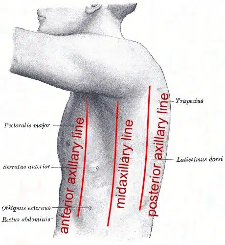
Figure 4‑7 Axillary lines
Figure 4‑8 shows a recommended electrode placement layout on the body. The reference electrode, RL (green), input should be placed on the top of the right leg. The LA (black) electrode should be placed in the “V6” ECG electrode position (i.e., on the top of the mid-axillary line, on the left side of the body, at the sixth inter-costal space). The RA (white) electrode should be placed at the same location on the right-hand side of the body.
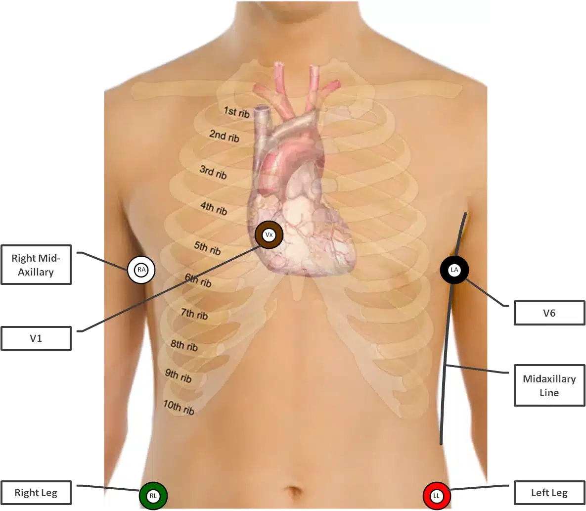
Figure 4‑8 Recommended electrode placement
Although inputs LL (red) and Vx (brown) are not required for respiration detection, both inputs can be used as additional ECG channels. If these are in use, it is recommended to connect these to the typical locations used for most clinical ECG electrode placements; the LL (red) input at the top of the left leg and the Vx (brown) input at the standard “V1” ECG electrode position (i.e., at the fourth inter-costal space, to the right of the sternum).
Note: In case Vx or LL are not connected to the body, make sure there is no electrode cable connected to the corresponding input on the Shimmer3 ECG unit as this can introduce additional noise in the system.
Table 4‑1 gives an overview of the input connectors and the recommended electrode positions for achieving the best respiration signal quality.
| Input | Electrode Position |
|---|---|
 |
Mid-Axillary line – right-hand side |
 |
Mid-Axillary line – left-hand side (“V6”) |
 |
Right Leg |
 |
Left Leg (Optional electrode) |
 |
V1 (Optional electrode) |
Table 4‑1 Input connectors and electrode positions
Configuration with Consensys
This section describes how to enable respiration detection with default settings using our Consensys software. See Advanced configuration below for advanced configuration when using software other than Consensys or non-default settings.
Figure 4‑9 shows the configuration menu that can be accessed through either MANAGE DEVICES or LIVE DATA.
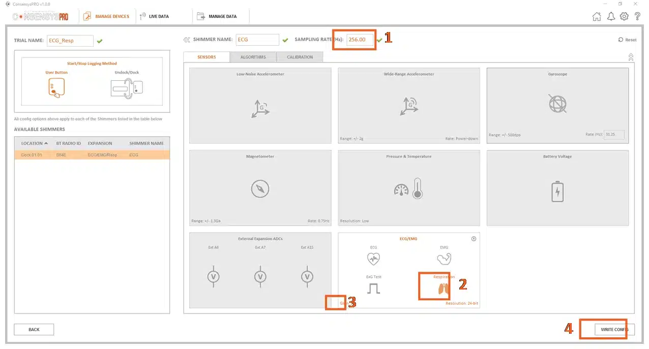
Figure 4‑9 Default Respiration Detection configuration.
Steps to enable respiration detection:
Set a minimum sample rate of 204.8Hz.
Enable “Respiration”.
Set the gain to 3.
Write the configuration.
For the default configuration the Respiration Detection Frequency is 32 kHz and Respiration Detection Phase is 112.5°.
Advanced configuration
This section describes how advanced configuration settings can be modified when the default configuration is not suitable or when software other than Consensys is used (e.g., Shimmer APIs/Instrument Drivers).
The Shimmer3 ECG unit contains two ADS1292R chips from Texas Instruments. These chips are fully configurable in software by setting the byte values of their ExG Configuration registers – also called “ExG Configuration Bytes” in Shimmer documentation (the ADS1292R datasheet: Texas Instruments, Low-Power, 2-Channel, 24-Bit Analog Front-End for Biopotential Measurements, 2012). The values of the ExG Configuration Bytes can be changed in the Consensys “Advanced ECG/EMG” menu, which can be accessed by clicking on the corresponding icon on the “ECG/EMG” configuration tile, see Figure 4‑10.
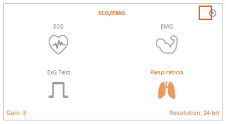
Figure 4‑10 Advanced ECG/EMG icon
The adjustable parameters for Respiration Detection are:
Respiration Detection Frequency; Bit 2 of register “RESP2”
Respiration Detection Phase; Bits[5:2] of register “RESP1”
Gain of Programmable Gain Amplifier (PGA); Bits[6:4] of registers “CH1SET” / “CH2SET”
These parameters can be changed by modifying the values of the ExG Configuration Bytes directly, or by using the drop-down menus highlighted in Figure 4‑11. The drop-down menu for the PGA gain can be found on the “ECG/EMG” configuration tile, see Figure 4‑9 or Figure 4‑10. For background information on the Respiration Detection signal, refer to (Texas Instruments, Respiration Rate Measurement Based on Impedance Pneumography, 2011).
For respiration detection the “Reference Electrode” needs to be set to “Fixed Potential”, see Figure 4‑11. (For non-Consensys users: Chip1 RLD_SENS = 0x20, Chip2 RLD_SENS = 0x00).
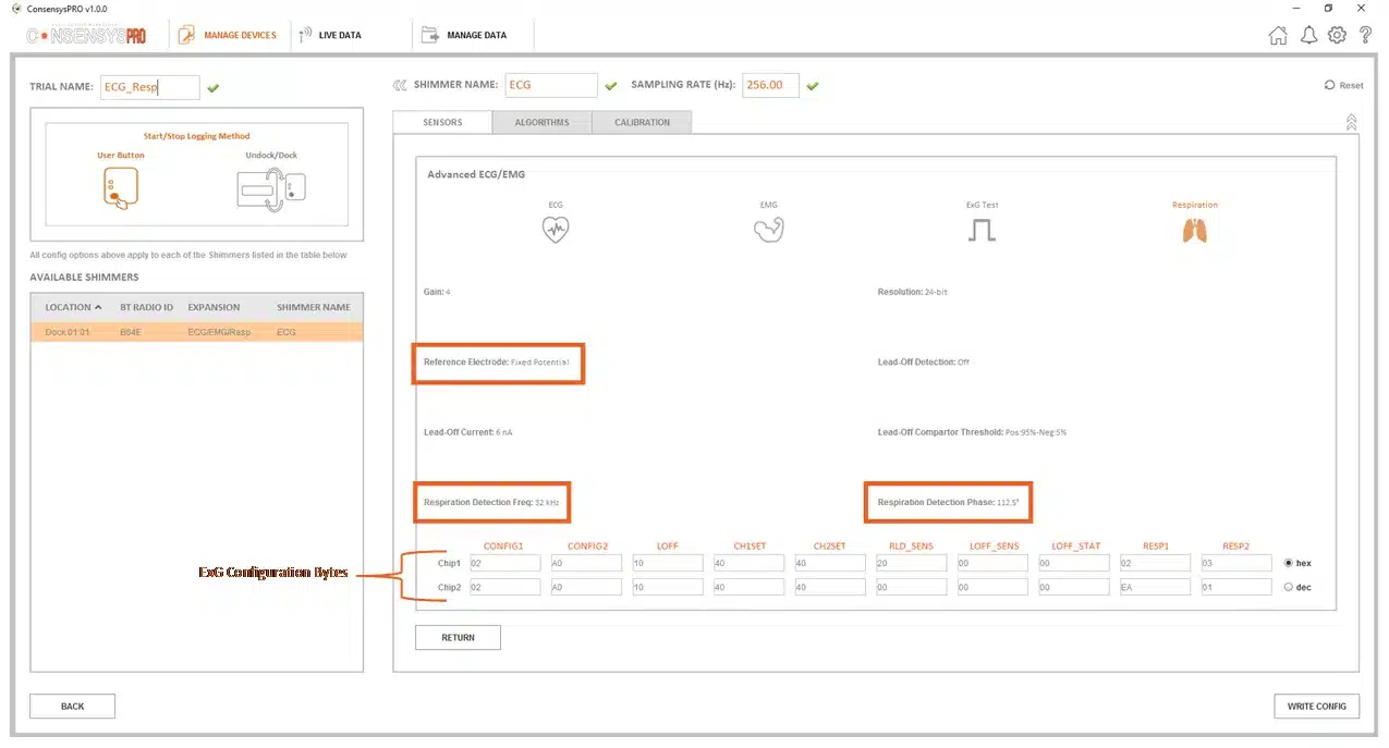
Figure 4‑11 Advanced ECG/EMG menu
Respiration Advanced chip configuration bytes:
For respiration detection, the configuration bytes of the ADS1292R chips need to be configured as per Figure 4‑12 below. This allows both chips to be synchronized at the same sampling clock and also reduces power consumption in SR47-4 and greater versions as a second internally generated clock does not need to be enabled (saving ).
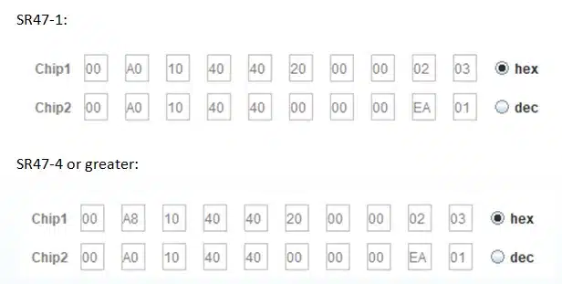
Figure 4‑12 Chip configuration
The recommended combinations of settings provided by Texas Instruments are listed in Table 4‑2. Alternatively, the user can experiment with values other than the ones recommended. Appendix 9.3 lists all the possible values of the Respiration Detection Frequency and the Respiration Detection Phase.
| Respiration Detection Frequency | Gain | Respiration Detection Phase |
|---|---|---|
| 32 kHz | 3 | 112.5° |
| 32 kHz | 4 | 135° |
| 64 kHz | 2 | 135° |
| 64 kHz | 3 | 157° |
Table 4‑2 Settings recommended by Texas Instruments
Example: post-processing the respiration signal
When the respiration detection circuitry is enabled, a very small high-frequency current is injected into the body of the test subject. This high-frequency current acts a carrier wave that is amplitude‑modulated by the low-frequency respiration signal, i.e., the signal of interest. The modulated signal is automatically demodulated within the Shimmer and the resulting respiration waveform is presented as an output channel from the Shimmer while streaming/logging, see page 3 of the Texas Instruments application note cited above for a block diagram of this concept. Since the ADS1292r chip does not contain a low-pass filter in the signal path between the demodulated respiration signal and the AD-converter (see page 3 of that application note), unwanted high-frequency content is still present in the signals. Post-processing the signals afterwards in software can isolate the low-frequency respiration and ECG signals.
In this example the recommended electrode placement and the default configuration settings (and a sampling rate of 512Hz) are used. Respiration signals are capture from a person carrying out the following actions:
breathing normally for almost 80 seconds
followed by three pronounced inhalations and exhalations
followed by another 30 seconds of normal breathing
followed by three pronounced inhalations and exhalations
Figure 4‑13 shows the resulting respiration signal after the signal has been post-processed using a low‑pass filter.
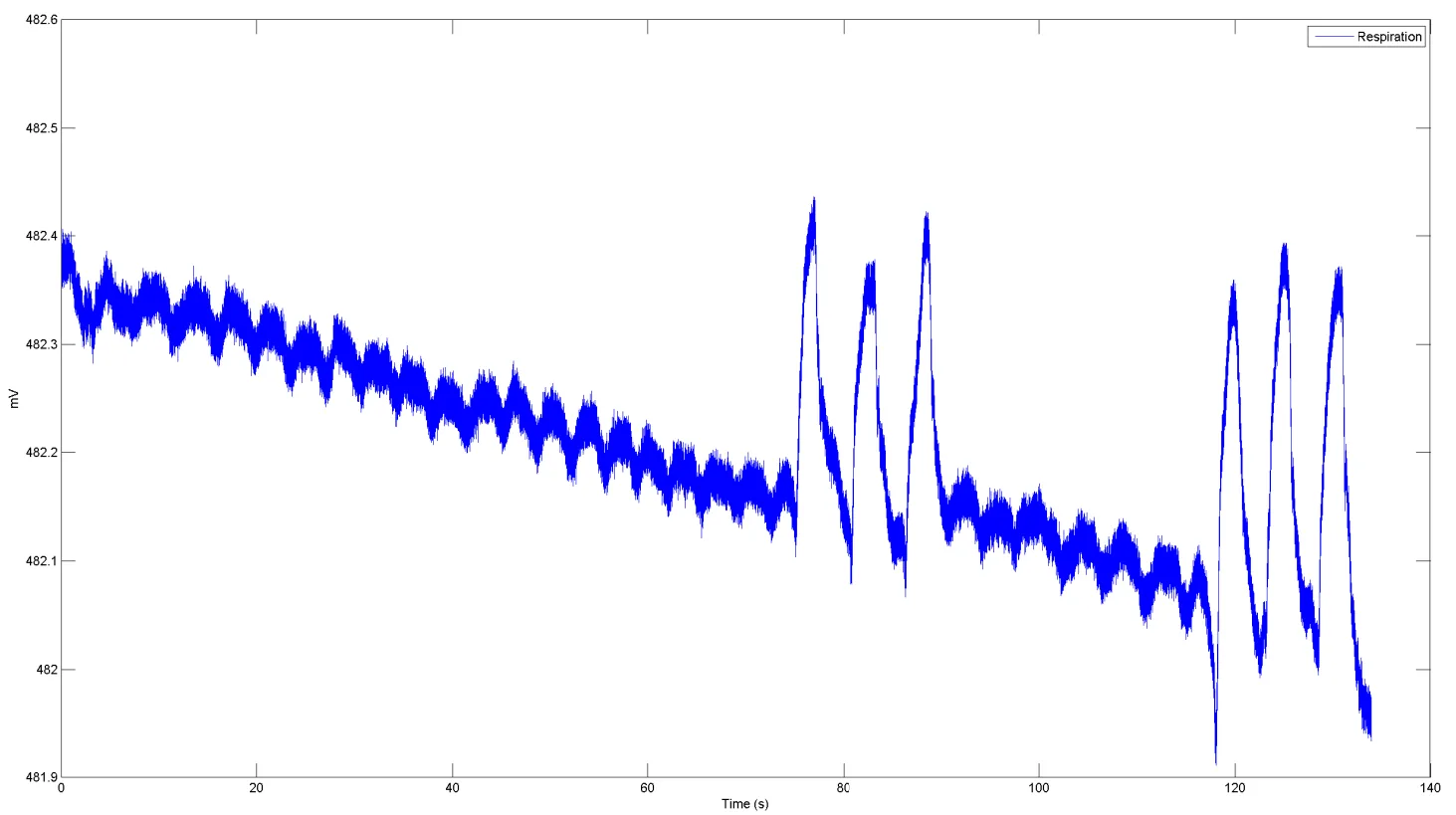
Figure 4‑13 Respiration signal
Figure 4‑14 zooms in on the last three pronounced inhalations and exhalations, before (top) and after filtering (bottom). The low-pass filter used to post-process the respiration signal is a low‑pass Blackman‑Windowed Sinc-filter with 120 taps and a cut-off frequency of 2Hz.
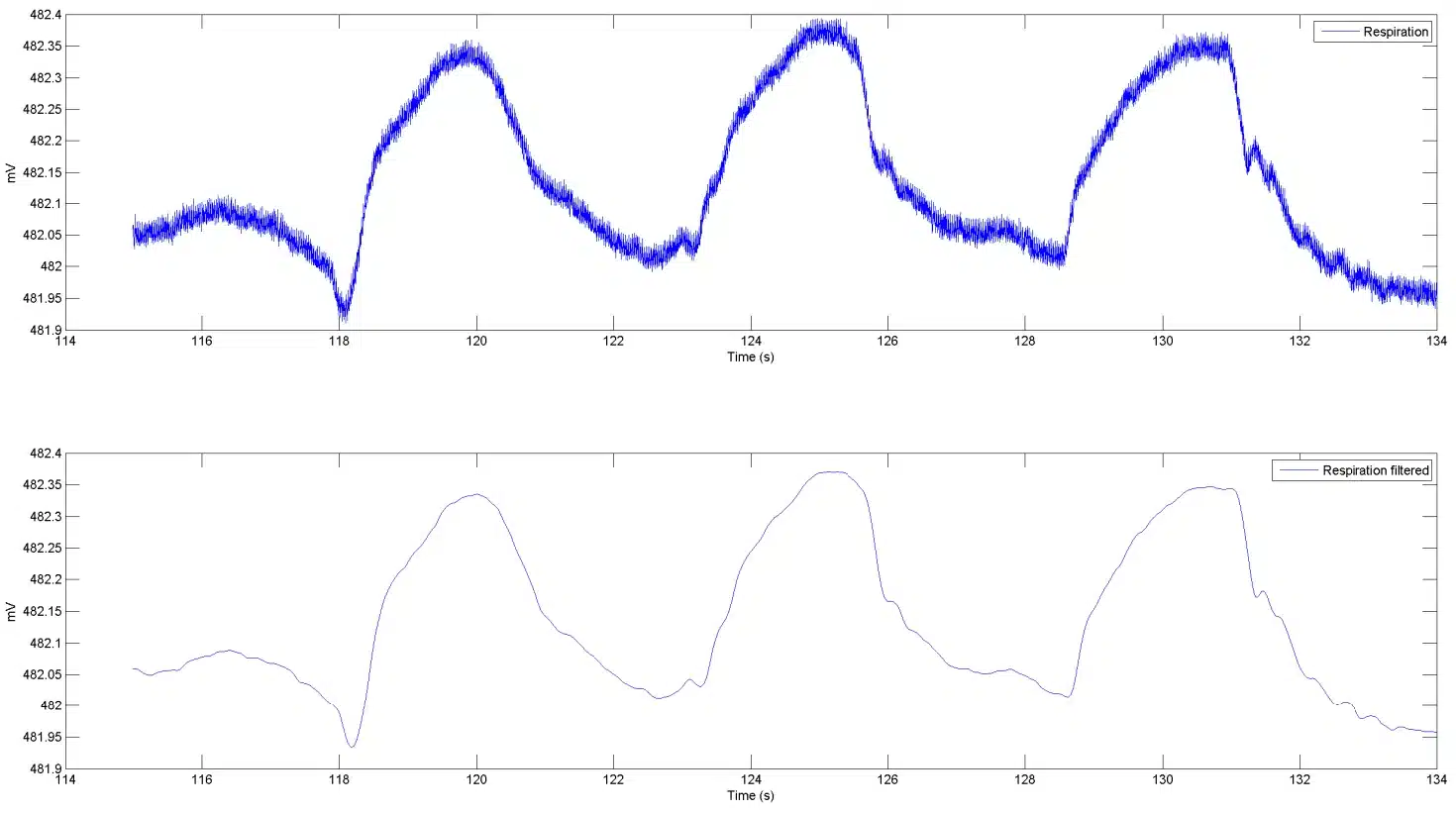
Figure 4‑14 Low-pass filtered respiration signal
Finally, Figure 4‑15 also includes the ECG “LL-RA” signal; before and after filtering. The filter used is a low‑pass Blackman‑Windowed Sinc-filter with 120 taps and a cut-off frequency of 30Hz.
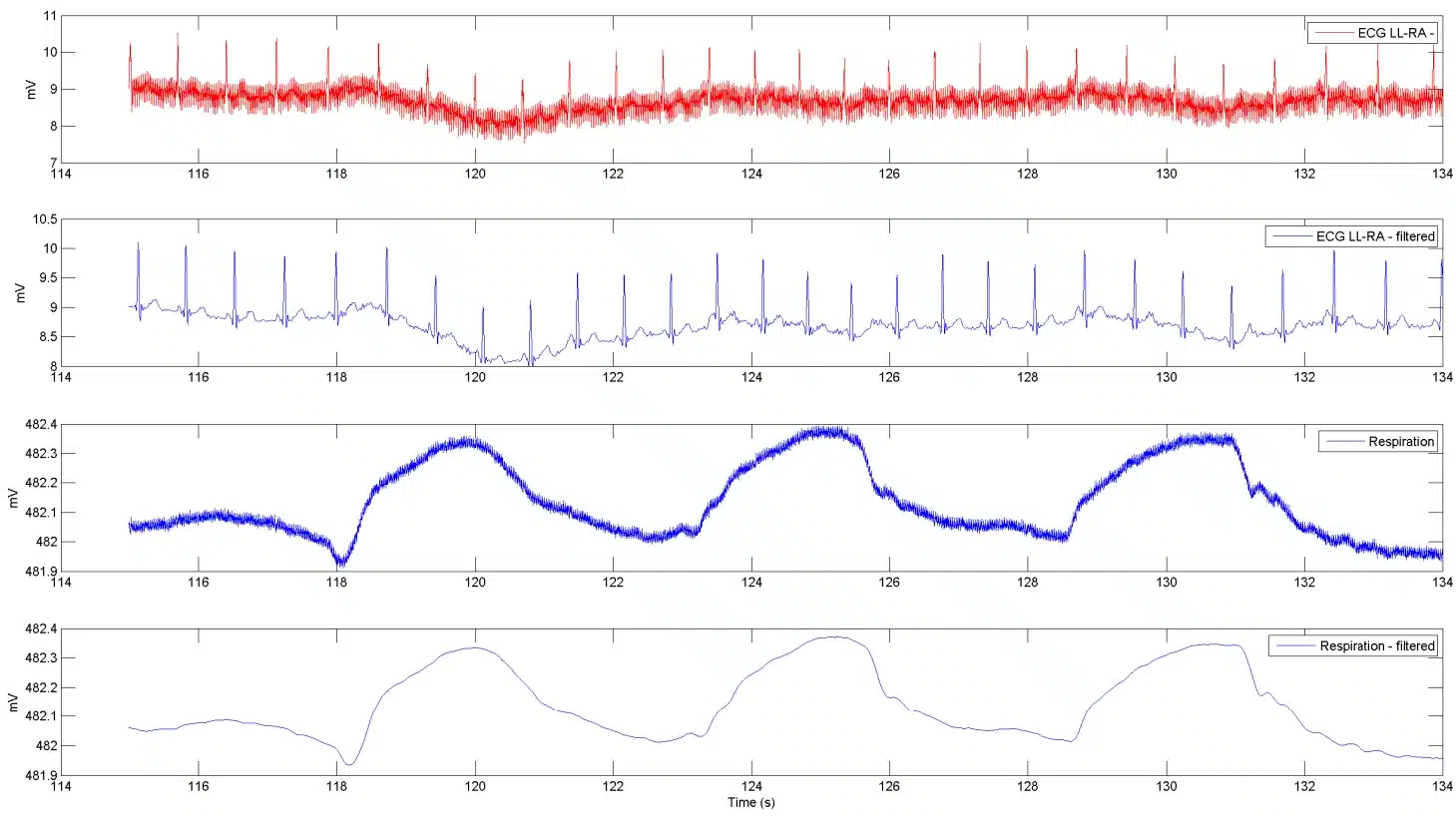
Figure 4‑15 ECG “LL-RA” and respiration
4.7. Using the Unit as Three Unipolar Inputs
The Shimmer3 ECG Unit and Shimmer3 EMG Unit can be configured to measure three unipolar inputs, instead of their usual two bipolar inputs (EMG) or two bipolar inputs and one unipolar input (ECG).
Overview
Figure 4‑16 gives a simplified block diagram of the internal operation of the Shimmer ECG/EMG unit when it is configured in Three-Unipolar Input mode. The three measurement electrodes are ExG Chip 1 Channel 2 (black), ExG Chip 1 Channel 1 (red) and ExG Chip 2 Channel 2 (brown). The reference electrode is configured to output a fixed voltage of about 1.5 V: half the ExG chips’ 3.0 V analogue supply, generated inside the ADS1292R. This sits half-way across the inputs’ range of approximately 0 V to 3 V, so the voltage under measurement can swing above or below it. The white connector is configured to be disconnected internally and so serves no purpose in this configuration.
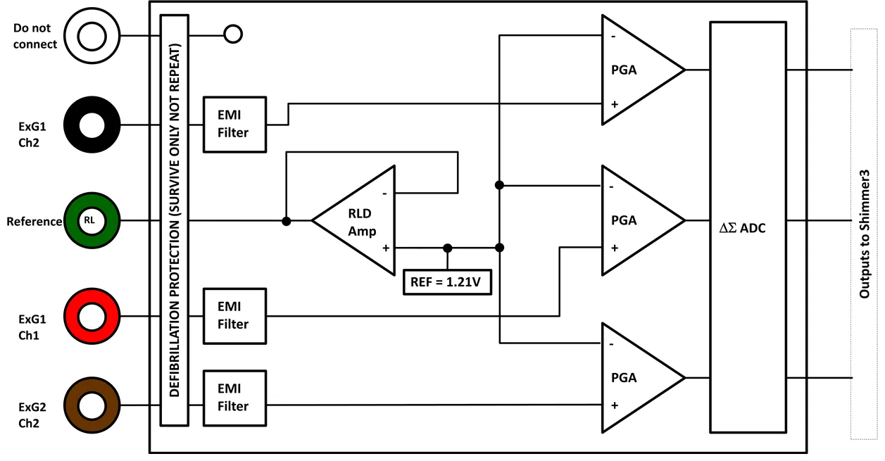
Figure 4‑16 Simplified block diagram
Electrodes:
White = Not internally connected.
Black = ExG Chip 1, Channel 2.
Green = Right-leg-driver (RLD) ≈ 1.5 V when reference potential is set to fixed
Red = ExG Chip 1, Channel 1.
Brown = ExG Chip 2, Channel 2.
Configuration
The easiest way to use the Three-Unipolar Input mode is to use our Consensys software (v1.1.0 or greater) as this software has built-in support for this mode. Alternatively, if using our Android software or our APIs or Instrumentation Drivers, Shimmer provides the ability to manually enter the required ExG configuration bytes in order to configure the Shimmer ECG/EMG unit for this mode.
Configuration using Consensys
- The Three-Unipolar input mode can be enabled by accessing the “Advanced ECG/EMG” configuration view on the ECG/EMG tile in Consensys v1.1.0 or greater, as shown below:
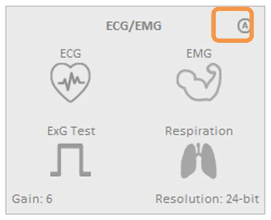
Figure 4‑17 The Consensys configuration tile for ExG (e.g., ECG/EMG) highlighting how to access the “Advanced ECG/EMG” menu.
- In the “Advanced ECG/EMG” menu, select the “Three Unipolar Inputs” option. You can now select your desired Gain and Resolution settings.
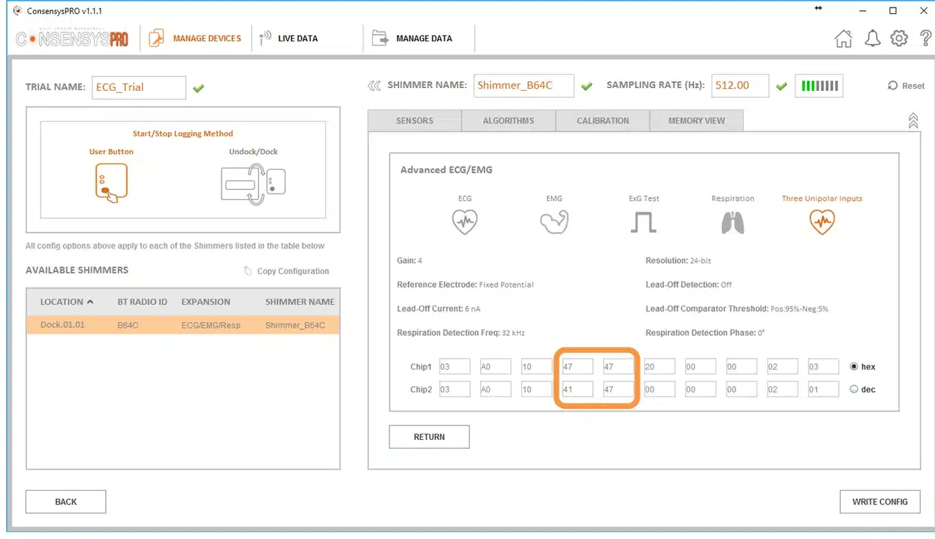
Figure 4‑18 The “Advanced ECG/EMG” menu as accessed through the Consensys software. Note that the highlighted bytes are the specific bytes that need to be set manually if configuring Shimmer units using ShimmerCapture for Android or a Shimmer API or Instrumentation Driver.
- The three output channels (ExG1_CH1, ExG1_CH2 and ExG2_CH2) corresponding to the three unipolar inputs will be then provided by the Shimmer while logging or streaming. For example, if streaming to Consensys, they appear as below:
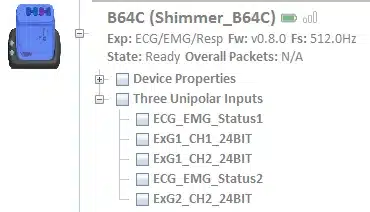
Figure 4‑19 The three unipolar channels while streaming to Consensys
Configuration using ShimmerCapture or an API
The ExG configuration bytes are 20 bytes, 10 for each ADS1292R chip; they are described in Section 3.3 and Table 3‑1. To put the unit into Three Unipolar Input mode, set the lower four bits (the MUX bits) of the CH1SET and CH2SET bytes on both chips as follows.
The required settings for the lower 4 bits of the MUX bytes are given in Table 4‑3. Chip2 Channel 1 is reserved for respiration circuitry and is therefore not used in the Three-Unipolar Input configuration – the setting of 0x1 below shorts the input to this channel. Each of the other channels (Chip 1 Channels 1 and 2 and Chip 2 Channel 2) require the same setting of 0x7. This configures them as unipolar input channels in-which they are measured with reference to the right-leg-driver (i.e., the fixed reference generated inside each chip, about 1.5 V).
Chip |
MUX1_3 / MUX2_3 |
MUX1_2 / MUX2_2 |
MUX1_1 / MUX2_1 |
MUX1_0 / MUX2_0 |
Hex. |
|
|---|---|---|---|---|---|---|
Bit 3 |
Bit 2 |
Bit 1 |
Bit 0 |
|||
Chip1 |
Channel 1 (byte 3) |
0 |
1 |
1 |
1 |
0x7 |
Channel 2 (byte 4) |
0 |
1 |
1 |
1 |
0x7 |
|
Chip2 |
Channel 1 (byte 13) |
0 |
0 |
0 |
1 |
0x1 |
Channel 2 (byte 14) |
0 |
1 |
1 |
1 |
0x7 |

Figure 4‑20 A zoomed in view of the MUX bytes as they appear in Consensys. Note that within each of these bytes, Bits [3-0] control the MUX settings, Bits [6-4] control each channel’s gain (i.e., Gain = 4 in this case) and Bit [7] is fixed at 0.
5. Hardware Considerations
5.1. Channel assignment
Note: For Shimmer3 ECG hardware purchased prior to July 2015, please refer to Appendix 9.1 of this document.
The ECG Unit contains two ADS1292R chips, which are referred to in the documentation as Chip1 and Chip2. When the MUX settings recommended in Section 3.3 of this document are configured, the channel assignment for ECG is as follows:
Chip1 Channel 1: (LL – RA) LL (Red) – RA (White).
Chip1 Channel 2: (LA – RA) LA (Black) – RA (White).
Chip2 Channel 1: Respiration demodulation (if configured, i.e. the defibrillation protection for input LA and RA has been removed).
Chip2 Channel 2: (Vx – RL) Vx (Brown) – RL (Green).
Right-Leg Drive: RL (Green).
5.2. Data considerations
The reference voltage for the ADS1292R chips is 2.42 V; this value should be used for conversion of raw data to voltage. The same 2.42 V reference is used on Shimmer3R.
6. Firmware Considerations
Shimmer3R: The Shimmer3R firmware is at https://github.com/ShimmerResearch/shimmer3r-firmware. The ExG configuration bytes and data format, shared by both generations, are documented in the configuration reference and the streaming data format reference.
Users with firmware development experience who wish to develop custom firmware for the ECG Unit should follow the example provided in the LogAndStream application, source code for which is available on the Shimmer Github repository at https://github.com/ShimmerResearch/shimmer3-firmware.
7. Troubleshooting
7.1. Verifying That Your ECG Unit Works
To verify that your ECG Unit is functioning correctly, the test signal in the ADS1292R chips should be used. Please refer to Section 3.3 of this document for details on how to configure each chip to output the test signal on one or both channels. When the test signal is configured, the output of each channel should follow the signal exactly (i.e. the output should be a DC signal or a square wave at 1 Hz, with an amplitude of ±1 mV).
You can view the signal in Consensys, available from the Shimmer website. On the ECG/EMG sensor tile, enable ExG Test in place of ECG, write the configuration and stream, as described in Streaming over Bluetooth in the Consensys User Guide. The test channels are Test_CHIP1_CH1, Test_CHIP1_CH2, Test_CHIP2_CH1 and Test_CHIP2_CH2.
A typical ECG sampling rate is 512 Hz but, for this test, any sampling rate will do. Start streaming and plot the test channels: the display should match the test signal (i.e. a DC signal or square wave depending on the configuration). If all channels are outputting the test signal properly, your ECG Unit is functioning correctly.
If the test signal is successfully transmitted to the channels but you continue to have problems with measure ECG signals, you should check electrode positioning and that the electrodes are all securely attached to both the skin and to the ECG Unit.
7.2. Signal Quality
A disconnected electrode or connector (lead-off) will adversely affect the measured ECG signal. This occurrence can be detected by the ADS1292R chips: see Lead-off detection configuration in Section 3.3.
8. References
[1] Oster, C.D. “Improving ECG trace quality.” Biomedical Instrumentation & Technology, 2000(34), p219-222.
[2] Smith, M. “Rx for ECG monitoring artifact.” Critical Care Nurse, 1984(4), p64-66.
[3] Pizzuti GP, Cifaldi S, Nolfe G (1985) ‘Digital sampling rate and ECG analysis’.
[4] Thaler, M.S. (2007) The only EKG book you’ll ever need, 5th ed., Philadelphia: Lippincott Williams & Wilkins.
[5] Köhler BU, Hennig C, Orglmeister R. (2002). The Principles of Software QRS Detection. IEEE ENG Med Biol Mag. 21 (1), p42-57.
[6] Pan J, Tompkins WJ. (1985). A Real-Time QRS Detection Algorithm. IEEE Transactions On Biomedical Engineering. 32 (3), p230-255.
[7] Lascu M, Lascu D. (2007). ‘LabVIEW Event Detection Using Pan-Tompkins Algorithm’. SSIP’07 Proceedings of the 7th WSEAS International Conference on Signal, Speech and Image Processing, p32-37.
[8] Portet F, Hernandez AI, Carrault G. (2005). Evaluation of real-time QRS detection algorithms in variable contexts. Medical & Biological Engineering and Computing. 43 (3), p381-387.
[9] Manikandan MS, Soman KP. (2012). A novel method for detecting R-peaks in ECG signal. *Biomedical Signal Processing and Control *. 7 (2), p118-128.
[10] Zidelmal, Zahia. (2011). QRS Detection Based on Wavelet Coefficients. Computer Methods and Programs in Biomedicine. 107 (3), p490-496.
[11] Last T, Nugent CD, Owens FJ. (2004). Multi-component Based Cross Correlation Beat Detection in ECG Analysis. Biomedical Engineering OnLine. 3 (26), p1-14.
9. Appendices
9.1. Legacy Hardware
The information in this section is relevant for Shimmer3 ECG hardware purchased prior to July 2015. As on current hardware, the two ADS1292R chips are referred to in the documentation as Chip1 and Chip2.
Channel assignment
When the MUX settings recommended in Section 3.3 of this document are configured, the channel assignment for ECG is as follows:
Chip1 Channel 1: (LL – RA) LL (Red) – RA (White).
Chip1 Channel 2: (LA – RA) LA (Black) – RA (White).
Chip2 Channel 1: Respiration demodulation (if configured).
Chip2 Channel 2: (Vx – RL) Vx (Brown) – RL (Green).
Right-Leg Drive: RL (Green).
Troubleshooting
Troubleshooting information that only applies to legacy hardware: If you do not see the test signal on one or all of the configured channels, you should ensure that the ECG Module is securely connected to the Shimmer3 mainboard. Please refer to Section 9.2 of this document for instructions on how to open the ECG module. You should then verify the configuration settings of your device.
For devices purchased between September 2014 and July 2015, the ECG Module is permanently fixed to the Shimmer3 mainboard. Removal of the expansion board from the mainboard should not be carried out under any circumstances. Doing so will cause damage to one or both of the boards and any necessary repairs will not be covered by warranty.
For devices purchased before September 1st, 2014, it was possible to disconnect the ECG Module from the Shimmer3 mainboard. For these devices, Shimmer recommends an adhesive to secure the connection between the Shimmer3 mainboard and Expansion Boards. The adhesive that is used by Shimmer during assembly is called Superdots (www.superdots.com). We use the Ultra Tak variety. With Superdots applied, the expansion boards can still be removed and swapped out, if required, as the adhesive does not go solid but has a rubbery consistency, allowing it to be removed. However, customers should remember that frequently removing expansion boards is not recommended and can cause damage to the connectors. Superdots also provides some shock absorbtion.
Shimmer fits the Superdots by stretching them around the edges of the Expansion Board. This ensures that the adhesive doesn’t prevent the connectors from making a good connection and there is enough adhesive to secure the boards together but not to interfere with the fit.
Note: Shimmer does not supply Superdots.
9.2. Opening the Shimmer3 expansion enclosure
Warning: Opening the enclosure of a sealed unit (ECG, EMG, GSR+, Bridge Amplifier+) voids its warranty.
Whilst the Shimmer3 enclosures can be opened to allow users to change the SD card, it is important to note that the plastic enclosures are not designed for regular opening and closing. In particular, it is recommended that the screws not be removed and reinserted on a regular basis as damage to the plastic by over-use of the screw mechanism will occur. Furthermore, the expansion board connectors can be damaged by disconnecting and reconnecting, resulting in the loss of communication with the expansion board.
For (legacy) devices purchased between September 2014 and July 2015, the ECG Module is permanently fixed to the Shimmer3 mainboard. Removal of the expansion board from the mainboard should not be carried out under any circumstances. Doing so will cause damage to one or both of the boards and any necessary repairs will not be covered by warranty.
For (legacy) devices purchased before September 1st, 2014, it is possible to disconnect the ECG Module from the Shimmer3 mainboard. Please note, however, that this is not recommended.
Whether the ECG Module is permanently fixed to the Shimmer3 mainboard or not, if the enclosure must be opened to replace the SD card, care must be taken not to damage the expansion board connection, which could result in loss of communication between the expansion board and the Shimmer3 mainboard. Please refer to the Shimmer assembly video on our YouTube channel5.
9.3. Respiration configuration bytes
The relevant ADS1292R configuration bytes for respiration measurement are listed in Table 9‑1, Table 9‑2 and Table 9‑3, for convenience. Please refer to the ADS1292R datasheet for more detailed information.
| On/Off | Mask (hex) | Byte Value (hex) | Byte Value (dec) |
|---|---|---|---|
| On | 0xC0 | 0xC0 | 192 |
| Off | 0xC0 | 0x00 | 0 |
Table 9‑1 Respiration Detection mode – Chip2 “RESP1” register
| Frequency | Mask (hex) | Byte Value (hex) | Byte Value (dec) |
|---|---|---|---|
| 32 kHz | 0x04 | 0x00 | 0 |
| 64 kHz | 0x04 | 0x04 | 4 |
Table 9‑2 Respiration Detection Frequency – Chip 2 “RESP2” register
| Phase @ 32kHz | Phase @ 64kHz | Mask (hex) | Byte Value (hex) | Byte Value (dec) |
|---|---|---|---|---|
| 0° | 0° | 0x3C | 0x00 | 0 |
| 11.25° | 22° | 0x3C | 0x04 | 4 |
| 22.5° | 45° | 0x3C | 0x08 | 8 |
| 33.75° | 67.5° | 0x3C | 0x0C | 12 |
| 45° | 90° | 0x3C | 0x10 | 16 |
| 56.25° | 112.5° | 0x3C | 0x14 | 20 |
| 67.5° | 135° | 0x3C | 0x18 | 24 |
| 78.75° | 157.5° | 0x3C | 0x1C | 28 |
| 90° | N/A | 0x3C | 0x20 | 32 |
| 101.25° | N/A | 0x3C | 0x24 | 36 |
| 112.5° | N/A | 0x3C | 0x28 | 40 |
| 123.75° | N/A | 0x3C | 0x2C | 44 |
| 135° | N/A | 0x3C | 0x30 | 48 |
| 146.25° | N/A | 0x3C | 0x34 | 52 |
| 157.5° | N/A | 0x3C | 0x38 | 56 |
| 168.75° | N/A | 0x3C | 0x3C | 60 |
Table 9‑3 Respiration Detection Phase – Chip 2 “RESP1” register
Calculated specification; exact value subject to environmental and component variation. ADS1292R is optimized for power with a differential input signal of approx. 300 mV when gain = 6.↩︎
Specifications from ADS1292R datasheet; exact value subject to environmental and component variation.↩︎
Any of the unipolar Vx leads (i.e. V1, V2, V3, V4, V5 and V6) can be measured on the ExG2 Ch2 channel by positioning the electrode at the Vx input with the appropriate placement on the body.↩︎
Note that for ECG Chip1, choosing 0111 for the RLD channel selection settings will also provide the Wilson’s Central Terminal voltage.↩︎
Legal notices
Legal Notices and Disclaimer
Redistribution IS permitted provided that the following conditions are met:
Redistributions must retain the copyright notice, and the following disclaimer. Redistributions in electronic form must reproduce the above copyright notice, this list of conditions and the following disclaimer in the documentation and/or other materials provided with the document.
Neither the name of Shimmer Research Ltd. nor the names of its contributors may be used to endorse or promote products derived from this document without specific prior written permission.
THIS DOCUMENT IS PROVIDED BY THE COPYRIGHT HOLDERS AND CONTRIBUTORS “AS IS” AND ANY EXPRESS OR IMPLIED WARRANTIES, INCLUDING, BUT NOT LIMITED TO, THE IMPLIED WARRANTIES OF MERCHANTABILITY AND FITNESS FOR A PARTICULAR PURPOSE ARE DISCLAIMED. IN NO EVENT SHALL THE COPYRIGHT OWNER OR CONTRIBUTORS BE LIABLE FOR ANY DIRECT, INDIRECT, INCIDENTAL, SPECIAL, EXEMPLARY, OR CONSEQUENTIAL DAMAGES (INCLUDING, BUT NOT LIMITED TO, PROCUREMENT OF SUBSTITUTE GOODS OR SERVICES; LOSS OF USE, DATA, OR PROFITS; OR BUSINESS INTERRUPTION) HOWEVER CAUSED AND ON ANY THEORY OF LIABILITY, WHETHER IN CONTRACT, STRICT LIABILITY, OR TORT (INCLUDING NEGLIGENCE OR OTHERWISE) ARISING IN ANY WAY OUT OF THE USE OF THIS DOCUMENT, EVEN IF ADVISED OF THE POSSIBILITY OF SUCH DAMAGE.
