
1. Introduction
This document is an accompaniment to the Shimmer PROTO3 Series of prototyping boards, whose aim is to help users to get started with the Shimmer PROTO3 Series products.
The Shimmer PROTO3 Series consists of two expansion boards for the Shimmer3 platform, which can be used to interface the Shimmer3 with an analogue output sensor, a digital output sensor, a serial UART or a parallel bus interface. Both connect to the Shimmer3 mainboard’s internal expansion connector, a surface-mount connector inside the enclosure, so fitting a board, or reaching its solder holes, means opening the enclosure:
PROTO3 Mini Expansion Board: Connects to the Shimmer3 via the internal expansion connectors; fits within the standard Shimmer3 enclosure.
PROTO3 Deluxe Expansion Board: Connects to the Shimmer3 via the internal expansion connectors; requires an extended Shimmer3 enclosure. Its two 3.5 mm 4-pole jacks can be reached from outside the enclosure.
Shimmer3R: The Shimmer3R PROTO3 Deluxe is a unified unit: the prototyping board and the Shimmer3R’s own electronics are one board, in place of an expansion board fitted to a mainboard. Shimmer3R has no internal expansion connector, so there is no Shimmer3R PROTO3 Mini. On a Shimmer3R the analog inputs keep their pins but have new names in Consensys and the Shimmer APIs, because Shimmer3R reads them through an external 12-bit ADC (TI ADS7028) with the same 0 V to 3 V range:
PROTO3 input (Shimmer3 name) Shimmer3R name A12 Int A0 A13 Int A1 A14 Int A2 A1 Int A3 Table 1‑1 Shimmer3R names for the PROTO3 analog inputs
Wherever this guide names A1, A12, A13 or A14, use the Shimmer3R name on a Shimmer3R.
The Shimmer3R PROTO3 Deluxe‘s own connections are in Shimmer3R PROTO3 Deluxe.
The PROTO3 series of boards enables users to incorporate additional functionality to the Shimmer, providing an outlet to develop their specific application to meet their own user requirements. The PROTO3 boards allow easy prototyping of 3rd party sensors or custom sensing solutions with Shimmer.
2. General Information
2.1. Pre-Requisites
A Shimmer3 module programmed with LogAndStream firmware, which streams data over Bluetooth and logs it to the SD card. Shimmer units are shipped with it, and Consensys installs updates.
A PROTO3 Expansion Board.
2.2. PROTO3 Series Features
Easy access to Shimmer3 microcontroller signals using wire holes or solder pads.
Shimmer PROTO3 Mini board fits inside standard Shimmer3 enclosure.
Shimmer PROTO3 Deluxe board includes 3.5mm jack connectors.
Connect an auxiliary power supply.
EEPROM for board identification and user storage.
2.3. Basic Overview
EEPROM
The EEPROM device on the Shimmer PROTO3 Series expansion boards has 2048 bytes of memory. Shimmer uses 16 bytes to store a board identifier that defines the hardware design and revision and is useful for debugging purposes. The other 2032 bytes can be used as the user sees fit, to store calibration parameters or other data. LogAndStream firmware from Shimmer includes commands to read and write the data on the EEPROM.
PROTO3 Deluxe
The PROTO3 Deluxe Expansion Board provides through-hole connections as well as two 3.5mm jacks, for interfacing with external devices, such as analog or digital sensors, from which the user may wish to measure data via the Shimmer3. For more details regarding the connections, refer to Section 3.1 of this document.
PROTO3 Mini
The PROTO3 Mini Expansion Board provides through-hole connections for interfacing with external devices, such as analog or digital sensors, from which the user may wish to measure data via the Shimmer3. For more details regarding the connections, refer to Section 3.1 of this document.
3. Hardware Considerations
3.1. Board Layout and Connections
PROTO3 Mini
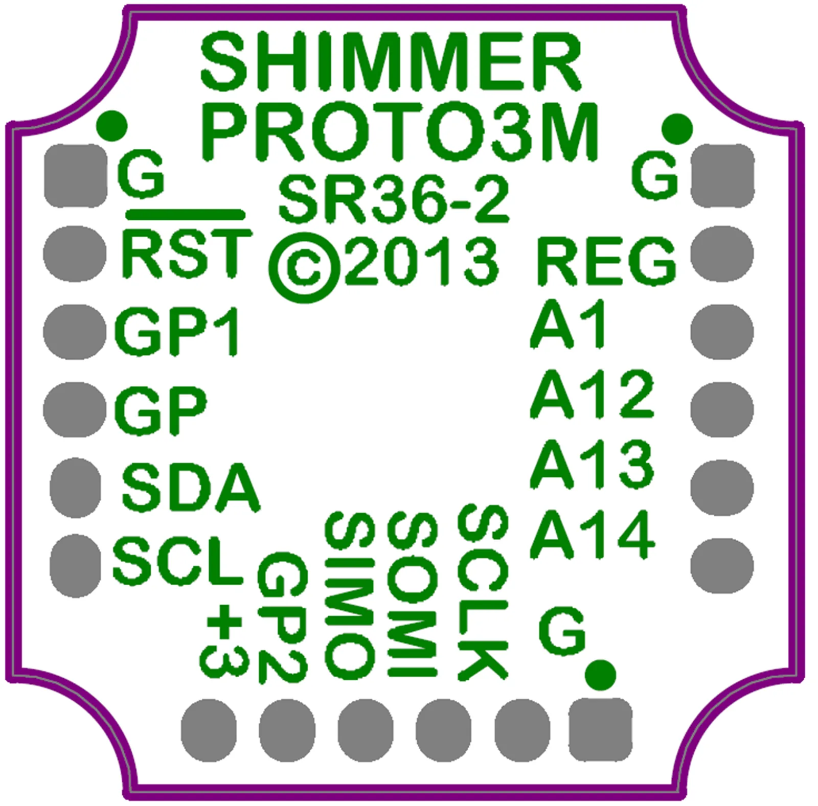
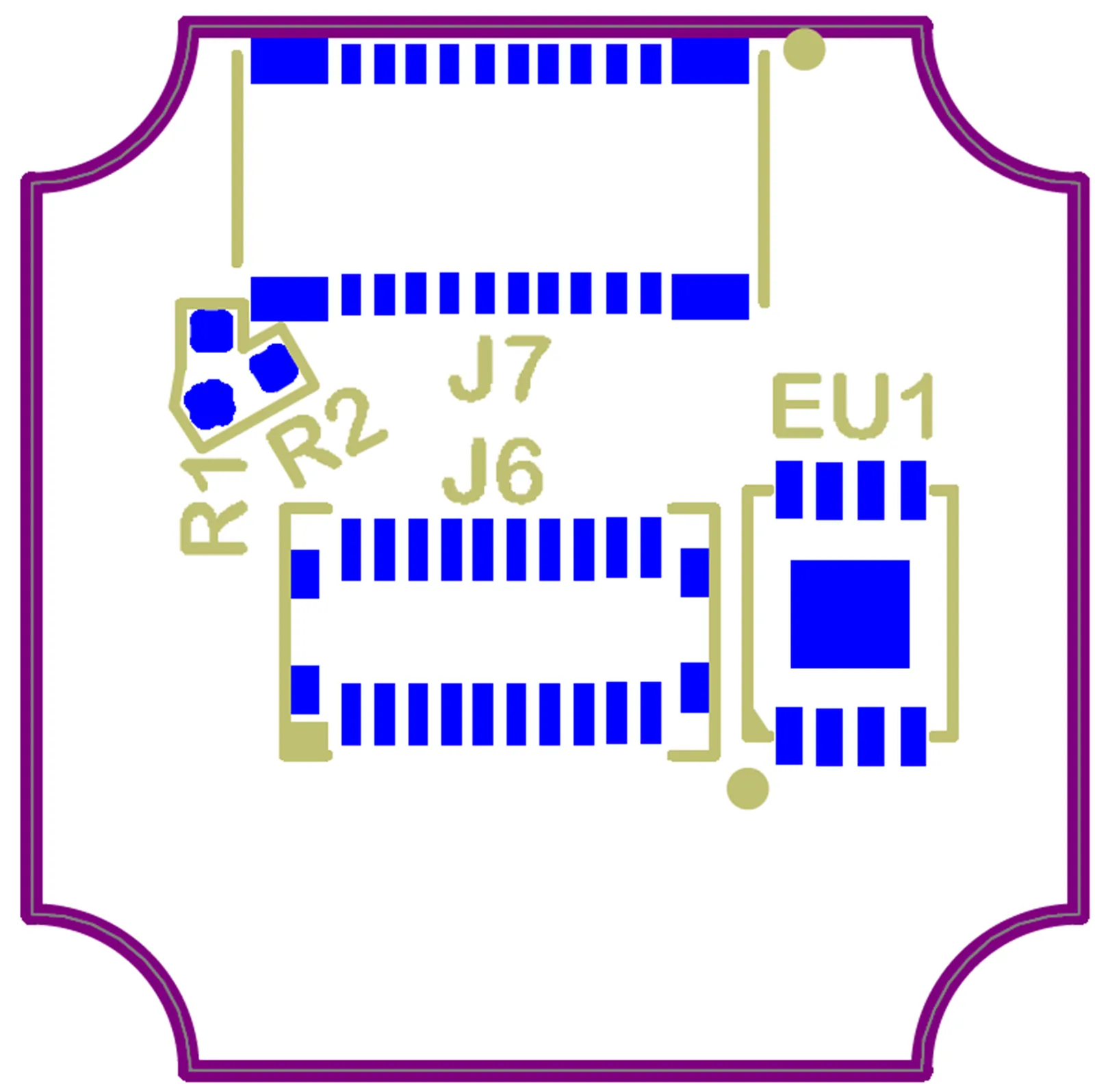
The board layout for the PROTO3 Mini Expansion Board is illustrated in Figure 3‑1, whilst connections for the wire holes on the board and their corresponding functions are listed in Table 3‑1. For details on the connections for J6 and J7, which connect the board to the Shimmer3 mainboard, please refer to the Shimmer3/3R User Manual, which can be downloaded from the Shimmer website.
| PCB Label | Connector Pin # | Shimmer3 Label | Function / Notes | Utilization detail |
|---|---|---|---|---|
| G | J1.1, J2.1, J3.1 | GND | Ground Connection | Shared |
| +3 | J2.6 | PV | +3.0V regulated voltage | Shared |
| RST | J3.2 | EXP_RESET_N | Digital output signal, typically used as a power-on-reset (POR) signal | Dedicated |
| GP | J3.4 | GPIO_INTERNAL | General purpose I/O pins | Dedicated |
| GP1 | J3.3 | GPIO_INTERNAL1 | General purpose I/O pins | Dedicated |
| GP2 | J2.5 | GPIO_INTERNAL2 | General purpose I/O pins | Dedicated |
| SDA | J3.5 | SB_SDA | USART B0 | Shared |
| SCL | J3.6 | SB_SCL | USART B0 | Shared |
| SIMO | J2.4 | SA_SIMO_TXD | USART A0 | Shared1 |
| SOMI | J2.3 | SA_SOMI_RXD | USART A0 | Shared3 |
| SCLK | J2.2 | SA_CLK | USART A0 SPI Clock | Dedicated |
| A1 | J1.3 | ADC1 | Analog-to-digital converter channel | Dedicated |
| A12 | J1.3 | ADC12 | Analog-to-digital converter channel | Dedicated |
| A13 | J1.5 | ADC13 | Analog-to-digital converter channel | Dedicated |
| A14 | J1.6 | ADC14 | Analog-to-digital converter channel | Dedicated |
| REG | J1.2 | PV_REG | Voltage regulator input voltage | Shared |
Figure 3‑1 Board Layout for PROTO3 Mini Expansion Board: top view (left) and bottom view (right)
Table 3‑1 Shimmer PROTO3 Mini Expansion Board connections
PROTO3 Deluxe
The board layout for the PROTO3 Deluxe Expansion Board is illustrated in Figure 3‑2, whilst connections for the wire holes on the board and their corresponding functions are listed in Table 3‑2. Once again, for details on the connections for J6 and J7, which connect the board to the Shimmer3 mainboard, please refer to the Shimmer3/3R User Manual, which can be downloaded from the Shimmer website.
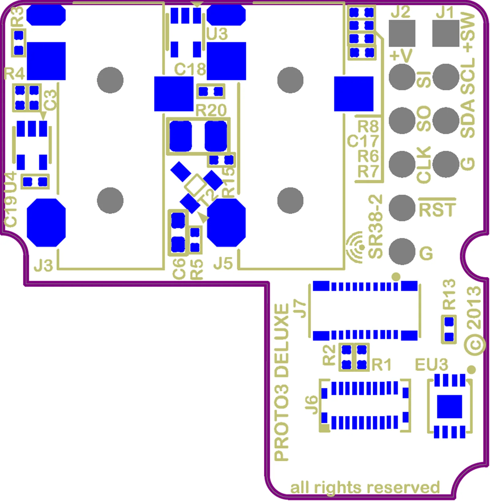
Figure 3‑2 Board Layout for PROTO3 Deluxe Expansion Board
| PCB Label | Connector Pin # | Shimmer3 Label | Function / Notes | Utilization detail |
|---|---|---|---|---|
| G | J1.4, J2.6 | GND | Ground Connection | Shared |
| +V | J1.1 | PV_I2C | I2C Peripheral power (use with I2C peripherals) | Shared |
| +SW | J2.1 | PV | +3.0V regulated voltage. | Shared |
| RST | J2.5 | EXP_RESET_N | Digital output signal, typically used as a power-on-reset (POR) signal | Dedicated |
| SDA | J1.3 | SB_SDA | USART B0; install R2 (digital mode). | Shared |
| SCL | J1.2 | SB_SCL | USART B0; install R1 (digital mode). | Shared |
| SI | J2.2 | SA_SIMO_TXD | USART A0. | Shared2 |
| SO | J2.3 | SA_SOMI_RXD | USART A0. | Shared4 |
| CLK | J2.4 | SA_CLK | USART A0 SPI Clock | Dedicated |
| J3 | – | – | 3.5 mm jack connector | See Table 3‑3 |
| J5 | – | – | 3.5 mm jack connector | See Table 3‑4 |
Table 3‑2 Shimmer PROTO3 Deluxe Expansion Board connections The 3.5 mm 4-position jack connectors, J3 and J5, have four connections each, as labelled in Figure 3‑3. Their connections are listed in Table 3‑3 and Table 3‑4.
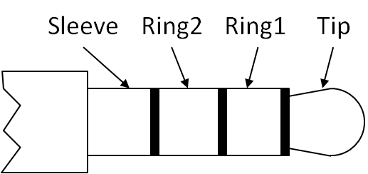
Figure 3‑3 3.5mm 4-position jack connector labels
| Connector Pin # | Shimmer3 Label | Function / Notes | Utilization detail |
|---|---|---|---|
| Sleeve (J3.1) | GND | Ground Connection | Shared |
| Tip (J3.2) | ADC13 | Analog-to-digital converter output channels (analog mode). | Dedicated |
| SB_SCL | USART B0; install R1 (digital mode). | Shared | |
| Ring1 (J3.3) | ADC12 | Analog-to-digital converter output channels (analog mode). | Dedicated |
| SB_SDA | USART B0; install R2 (digital mode). | Shared | |
| Ring2 (J3.4) | PV_REG | Voltage regulator input voltage; install R5. | Shared |
| PV_SW | 3V if EXP_RESET_N is high. | Dedicated |
| Connector Pin # | Shimmer3 Label | Function / Notes | Utilization detail |
|---|---|---|---|
| Sleeve (J5.1) | GND | Ground Connection | Shared |
| Tip (J5.2) | ADC1 | Analog-to-digital converter output channels (analog mode). | Dedicated |
| PWM0 | Install PWM components. | Dedicated via GP | |
| Ring1 (J5.3) | ADC14 | Analog-to-digital converter output channels (analog mode). | Dedicated |
| Ring2 (J5.4) | PV_REGSW | Voltage regulator input voltage; install R6. | Dedicated via GP1 |
| PV_SW | 3V if EXP_RESET_N is high. | Dedicated |
Shimmer3R PROTO3 Deluxe
The Shimmer3R PROTO3 Deluxe (board SR38-4) is one board, so it has no J6 and J7 mainboard connectors. Its wire holes are in two rows, J10 and J4, each with pin 1 on the square pad, beside the dot (Figure 3‑2R, Table 3‑2R), and it has two 3.5 mm 4-position jacks, printed J2 and J3 on the board (Table 3‑3R), labelled as in Figure 3‑3. The signal names are the Shimmer3R’s own; SPI3 and I2C4 are the Shimmer3R processor’s SPI and I2C buses brought out to the holes.
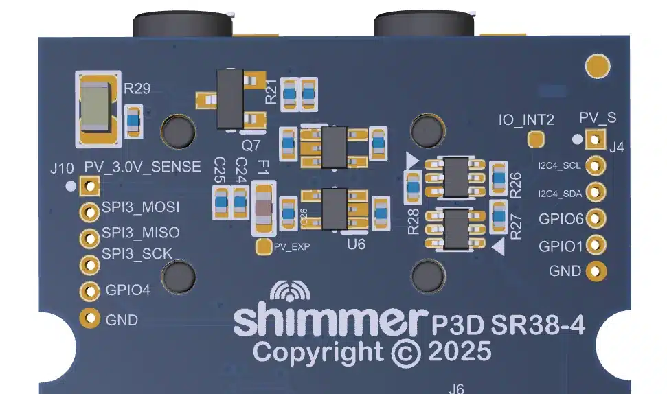
Figure 3‑2R Shimmer3R PROTO3 Deluxe wire holes
| Connector Pin # | Board label | Function |
|---|---|---|
| J10.1 | PV_3.0V_SENSE | +3.0 V sensor supply (see below) |
| J10.2 | SPI3_MOSI | SPI data out (from the Shimmer3R) |
| J10.3 | SPI3_MISO | SPI data in (to the Shimmer3R) |
| J10.4 | SPI3_SCK | SPI clock |
| J10.5 | GPIO4 | General purpose I/O (processor pin PB2) |
| J10.6 | GND | Ground |
| J4.1 | PV_S | +3.0 V sensor I/O supply, PV_SENSE_IO (see below) |
| J4.2 | I2C4_SCL | I2C clock; 4.7 kΩ pull-up to PV_SW |
| J4.3 | I2C4_SDA | I2C data; 4.7 kΩ pull-up to PV_SW |
| J4.4 | GPIO6 | General purpose I/O (processor pin PA4) |
| J4.5 | GPIO1 | General purpose I/O (processor pin PD4) |
| J4.6 | GND | Ground |
Table 3‑2R Shimmer3R PROTO3 Deluxe wire-hole connections The two supplies on pin 1 come from the Shimmer3R’s sensor power: PV_3.0V_SENSE is the 3.0 V sensor regulator and PV_S the 3.0 V sensor I/O rail. Both are on while the Shimmer3R streams or logs (and briefly while it reads its battery or memory), and off otherwise, so a circuit powered from them is off when the Shimmer3R is idle. Draw as little current from them as you can: they also power the Shimmer3R’s own sensors.
| Jack | Contact | Signal | Function / Notes |
|---|---|---|---|
| J2 | Tip | Int A1, or I2C4 SCL | Analogue input Int A1. In I2C mode, the I2C clock |
| J2 | Ring1 | Int A0, or I2C4 SDA | Analogue input Int A0. In I2C mode, the I2C data line |
| J2 | Ring2 | PV_SW | +3.0 V regulated supply, switched (see below) |
| J2 | Sleeve | GND | Ground |
| J3 | Tip | Int A3 | Analogue input Int A3 |
| J3 | Ring1 | Int A2 | Analogue input Int A2 |
| J3 | Ring2 | PV_SW | +3.0 V regulated supply, switched (see below) |
| J3 | Sleeve | GND | Ground |
Table 3‑3R Shimmer3R PROTO3 Deluxe jack connections PV_SW, on Ring2 of both jacks, is on only while the Shimmer3R is streaming or logging with Internal Expansion Power enabled in its configuration. Enable it to power a sensor from the jack.
J2’s I2C mode needs no change to the board: two analogue switches connect J2’s tip and Ring1 to the I2C4 bus, which has 4.7 kΩ pull-ups to PV_SW, when the processor turns them on. LogAndStream keeps them off, so J2 works as two analogue inputs; using J2 for I2C needs firmware that turns them on (contact us).
3.2. Hardware configuration options
PROTO3 Mini
All boards ship with R1 installed, providing a connection to PV_REG at J1.2.
If it is desirable to use PV_I2C at J1.2, remove R1 and install a zero-Ohm resistor for R2 (see Figure 3‑1, bottom view).
PROTO3 Deluxe
Two of the inputs of the J3 3.5mm jack can be analog or digital, depending on the board configuration. See Section 3.1 for details of the connections for J3 and other board connectors.
All boards ship with analog configuration by default; this configuration can be recognised by checking that R1 and R2 are not populated (see Figure 3‑2, between J6 and J7).
To switch to digital configuration, a zero-Ohm resistor should be installed for each of R1 and R2.
Shimmer3R: on the Shimmer3R PROTO3 Deluxe, J2 switches between analogue and I2C under processor control, with no resistors to change (Shimmer3R PROTO3 Deluxe).
There is also a PWM option for the PROTO3 Deluxe Expansion Board, and for the Shimmer3R PROTO3 Deluxe on J3. Users who require PWM functionality should contact Shimmer prior to purchase to discuss the specific requirements for their application, as factors such as end-user load and control signal filtering will determine the values of certain hardware components.
4. Using the Shimmer PROTO3 Series (Typical Applications)
4.1. Connecting an Analog Output Sensor
Data from an analog output sensor can be passed to the ADC lines on the Shimmer3 via the PROTO3 Series expansion boards.
If the sensor is to be powered via the PROTO3 Mini Expansion Board or PROTO3 Deluxe Expansion Board, the user should refer to the sensor specification to ensure that +3V is suitable for the power supply connection to the sensor. Connect the 3V and GND connections to the relevant points on the sensor.
The output of the sensor should be connected to either of the A1, A12, A13 or A14 ADC inputs. If the sensor output is outside of the range of the Shimmer ADC (0V – 3V max) an attenuator must be added. It is the user’s responsibility to add the required attenuation and/or voltage shifting circuitry.
Connections to the ADC channels can be made directly to the PROTO3 Mini Expansion Board through-hole connections or via a 3.5mm 4-position jack to the PROTO3 Deluxe Expansion Board.
Any remaining GPIO pins can be used to configure control pins on the sensor. Verify the configuration of any of these pins in the Shimmer application code.
4.2. Connecting a Digital Sensor using the I2C interface
Following the tables in Section 3.1, connect the sensor to SCL, SDA, GND and the desired power connection.
When using USART B0 bus, the I2C bus is shared with the inertial sensors on the Shimmer3. The Shimmer3 board has 10kΩ pull-up resistors installed. Unless the sensor datasheet specifies otherwise, any pull-ups on the sensor (sometimes present on evaluation boards) should be removed or parts should be replaced with a value calculated based on parallel combination with 10kΩ resistors on Shimmer3 board. Care must be taken to ensure proper bus multiplexing and timing margin.
4.3. Connecting a Digital Sensor using the SPI interface
Paying attention to the required master-slave relationship in your application (Shimmer is usually master), connect up the SI, SO, and CLK pins. Use another GPIO pin as a Chip Select to complete the digital interface. The UART0 module will need to be configured for SPI mode.
The USART A0 SPI interface is dedicated to expansion to allow robust communication with peripherals, even those that are not designed to support multiple slaves.
Any remaining GPIO pins can be used to configure control pins on the sensor. Verify the configuration of any of these pins in the Shimmer application code.
4.4. Using the PROTO3 Deluxe 3.5mm jack interface
The PROTO3 Deluxe Expansion Board includes two 3.5 mm 4-position jacks that can be used to interface external sensors with analog or digital channels on the Shimmer3.
In analog configuration (the default configuration for all shipped units), the J3 jack provides an interface with channels A12 and A13, whilst the J5 jack provides an interface with channels A1 and A14 of the ADC; both jacks provide 3V and GND connections.
Example: Optical Pulse Sensing via PROTO3 Deluxe Expansion Board
The Shimmer Optical Pulse Sensor plugs into either jack, with the PROTO3 Deluxe Expansion Board in analog configuration (see Section 3.2); its PPG signal, on pin 2 (Tip), is read on the A13 channel (J3) or the A1 channel (J5) of the Shimmer3 ADC. The Optical Pulse Sensor User Guide describes the probe and how to use it.
Shimmer3R: On a Shimmer3R the same jacks give Int A1 (J3) or Int A3 (J5). In Consensys the PPG input choices “Int A13 / Int A12” and “Int A1 / Int A14” appear as “Int A1 / Int A0” and “Int A3 / Int A2”.
Enable the 3V expansion power to power the probe, in Consensys or the Shimmer APIs and instrument drivers.
4.5. Connecting to a Serial UART
Similar to the SPI directions above, the UART0 module must be configured for UART operation.
The output signals will be digital at a 3.0V reference, commonly called “logic level” and used by most IC peripherals such as low-power radio modules or cellular modems.
A level shifter IC or RS-232 level shifter may be used to interface with instrumentation or other computers. Pay careful attention to TXD and RXD orientation.
Some peripherals utilize 3.3V signalling. It is required to place a voltage dropping device such as a diode in series with the output of the peripheral to prevent damage to the Shimmer.
4.6. Connecting a Parallel Bus interface
To use a parallel bus interface, most pins will need to be configured as GPIO instead of the default functionality. Up to a 13-pin bus can be configured but simultaneous operation with the Shimmer’s integrated inertial sensors may reduce the number of free signals. Only pins connected to Port0, Port1, or Port2 can generate system interrupts.
4.7. Connecting an External Power Battery Pack
The PV_REG pad can be used to connect a battery pack or power supply. This power supply will not charge the Shimmer battery and must be isolated by a Schottky diode when the Shimmer battery is also in use. This Schottky diode should be included in the users circuitry.
Note: Do not exceed 5.5VDC irreversible damage will occur to the Shimmer
When operating without a Shimmer battery, the recommended input voltage range is 3.1-5.0V
When operating with a Shimmer battery, the recommended input voltage range after an isolation diode is 4-5.0V
For example, a battery pack consisting of 3 “D” alkaline cells in series is used instead of the stock Shimmer battery. The resulting voltage will be 4.5V at start. The resulting battery pack will have over 18000mAh capacity. A Shimmer application burning 25mA will run for over 2 years.
5. Firmware Considerations
5.1. Multifunction pins
The MSP430 processor uses multifunction pins. The functionality of the pin depends on firmware configuration. For more information please refer to the MSP430 programmers guide and reference code. For anything else, contact us through our contact page.
6. Appendices
6.1. Opening or assembling the PROTO3 Deluxe enclosure
Whilst the Shimmer3 enclosures can be opened to allow hardware reconfiguration of the device (e.g. adding an expansion board), it is important to note that the plastic enclosures are not designed for regular opening and closing. In particular, it is recommended that the screws not be removed and reinserted on a regular basis as damage to the plastic by over-use of the screw mechanism will occur.
Please, consider your configurations carefully to minimise the number of hardware reconfigurations you will need to carry out.
The following instructions should be used as a guide for opening and closing the Shimmer3 expansion enclosure and inserting the PROTO3 Deluxe Expansion Board.
For instructions on opening and closing the standard Shimmer3 enclosure please refer to the Shimmer3/3R User Manual.
Assembling the enclosure
Ensure that you have all of the required plastic parts as shown in Figure 6‑1, as well as two long (M2.0 x 8mm) and two short (M1.8 x 6mm) screws.
Assemble the orange clip fittings in the bottom of the enclosure (these are both the same so it doesn’t matter which one goes to which side), as shown in Figure 6‑2.
Install the power switch cap, as shown in Figure 6‑2.
Place the main circuit board, with the battery attached to the underside, into the bottom of the enclosure, see Figure 6‑3.
The bottom of the enclosure has a plastic divider to hold the battery in place; ensure that the battery is fitted beside this divider.
Ensure that the power switch actuator sits in the notch on the power switch cap and that the dock connector sits neatly into its slot.
Ensure that the battery wires are fully underneath the circuit board and not obstructing the screw positions.
The orange clip fittings are designed to hold the circuit board in place – it should be an exact fit.
Loosely place the PROTO3 Deluxe Expansion Board (and optionally the SD-Card), with the connectors to the underside, into the left bottom of the enclosure as soon shown in Figure 6‑4.
Gently press the PROTO3 Deluxe Expansion Board in place as shown in Figure 6‑5.
Take care not to force the connectors, which can easily be damaged by mishandling.
If you find that the connection is not made, realign the expansion board connectors with the Shimmer3 connectors.
Carefully attach the top of the case as shown Figure 6‑6. When the top is in place, gently push down on the top to close.
- Do not force the top closed – if there is an obstruction, remove the top to clear the obstruction before trying again.
Tighten the screws in the underside of the enclosure. Before doing so, please read the notes below!
Note: there are two sizes of screws. Make sure to use the long (M2.0 x 8mm) screws at the end closest to the External Expansion Connector and use the short screws (M1.8 x 6mm) at the end closest to of the PROTO3 Deluxe Expansion Board .
Note: it is very important to hold the boss ends together while running in the screw. Do not let the screws draw the parts together as this could damage the enclosure.
Note: do not over-tighten the screws as they may damage the top of the enclosure; when the top of the screw is flush with the plastic, stop tightening.
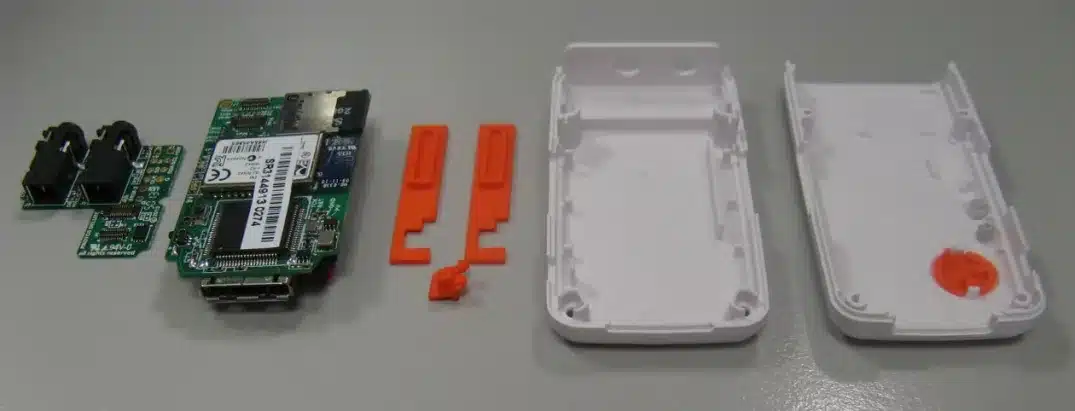
Figure 6‑1 Plastic enclosure parts
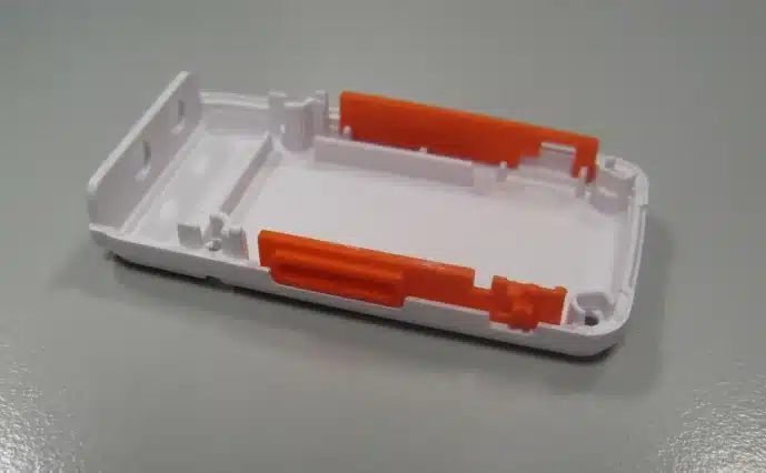
Figure 6‑2 Install Power Switch Cap
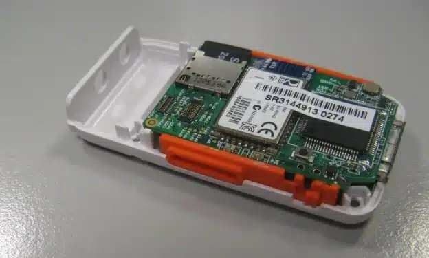
Figure 6‑3 Place the main circuit board
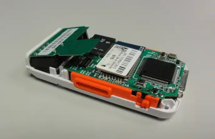
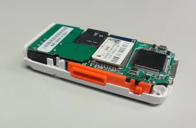
Figure 6‑4 Place the PROTO3 Deluxe Expansion Board
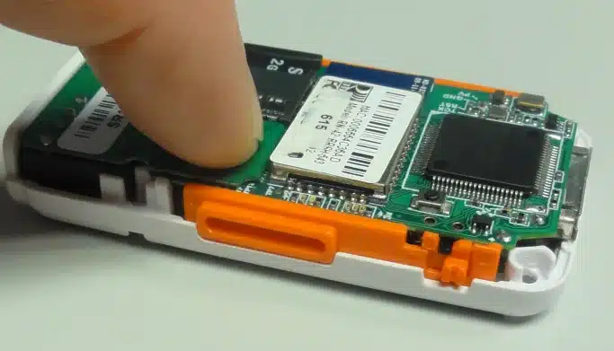
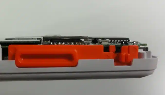
Figure 6‑5 Press the PROTO3 Deluxe Expansion Board in place
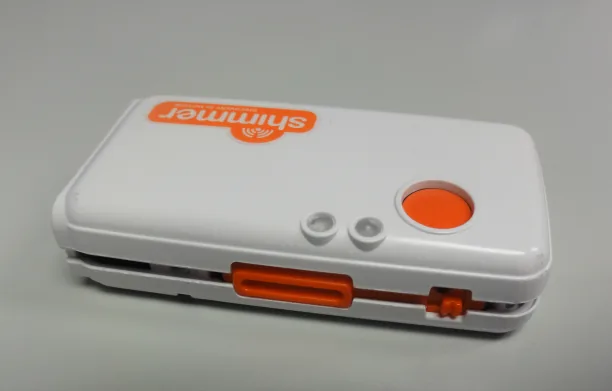
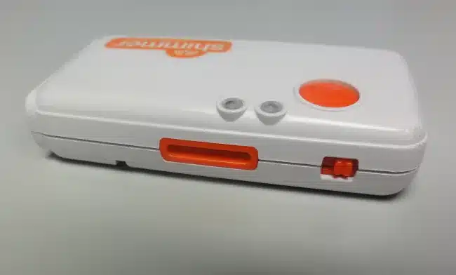
Figure 6‑6 Closing the enclosure
Opening the enclosure to change the SD card or exchange the expansion board
Unscrew the screws using a T6 screwdriver.
Turn the unit over so that the orange button is facing up.
Carefully remove the top of the case, opening from the end of the External Expansion Connector, see Figure 6‑7.
You now have access to the SD card slot and the expansion board.
If you need to remove the PROTO3 Deluxe Expansion Board , hold the main board and the enclosure between your thumb and index finger of your right hand, with your index finger at the bottom of the enclosure and your thumb on the area marked with the red ‘1‘ in Figure 6‑8, while pulling the expansion board away from the main board in the direction indicated by the arrows.
- Note: Do not use a screwdriver for disconnecting the expansion board from the main board as this could damage the boards.
If, for any reason you need to remove the circuit board from the case, lift it upward out of the case. The battery should be attached to the underside of the board – ensure that it comes out of the case with the board so as not to damage the connections.
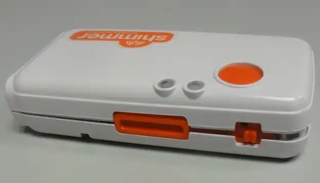
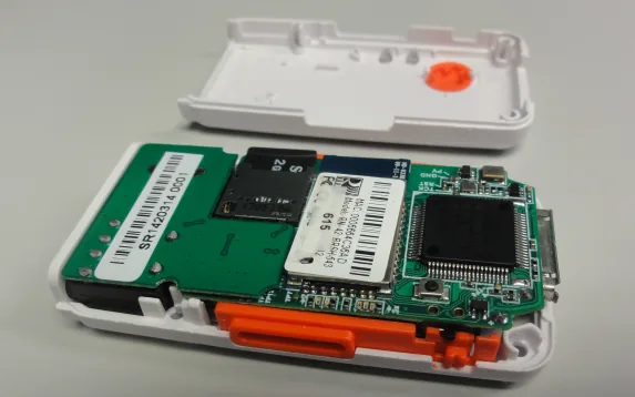
Figure 6‑7 Opening the enclosure
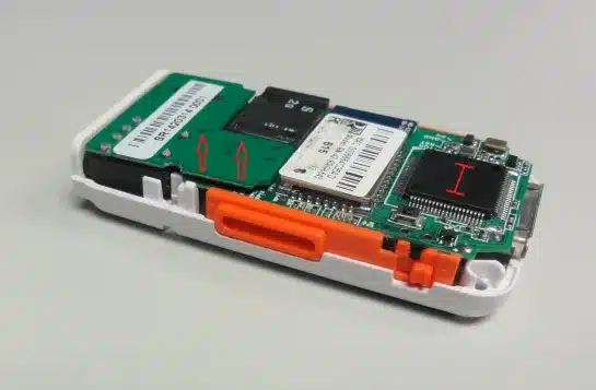
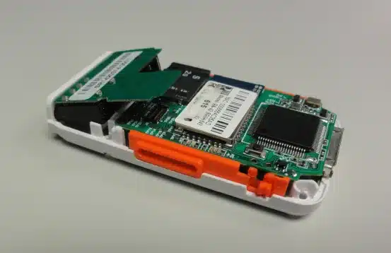
Figure 6‑8 Remove the PROTO3 Deluxe Expansion Board
6.2. Assembling the PROTO3 Mini Expansion Board
When using the PROTO3 Mini Expansion Board, the Shimmer3 enclosure may need to be modified to allow for user-connected components and/or wires. The following instructions should be followed to attach the PROTO3 Mini Expansion Board to the Shimmer3 mainboard.
Figure 6‑9, below, shows the PROTO3 Mini Expansion Board and Shimmer3.
To assemble:
Align the connectors J7 and J6 of the PROTO3 Mini Expansion Board and the Shimmer3 mainboard, as shown in Figure 6‑10.
Gently press the PROTO3 Mini Expansion Board. Figure 6‑11 shows the end result*.*
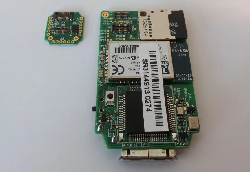
Figure 6‑9 PROTO3 Mini and Shimmer3
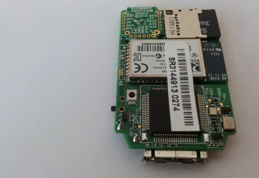
Figure 6‑10 PROTO3 Mini connected to Shimmer3 mainboard
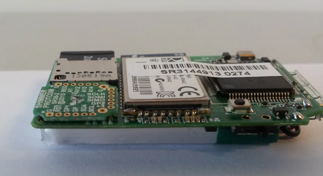
Figure 6‑11 PROTO3 Mini connected to Shimmer3 mainboard
To disassemble:
- Gently remove the PROTO3 Mini Expansion Board from the Shimmer3 mainboard by pulling upwards*.* Avoid any shearing forces which will damage the connectors.
Newer Shimmer3 mainboard (SR31-7) users:
Customers attaching the Proto3 Mini to newer versions of the Shimmer3 IMU unit (i.e., the SR31-7) need to update the board version for the device to function correctly in software (e.g., Consensys).
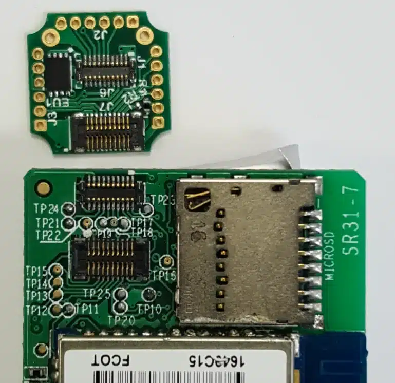
Figure 6‑12 PROTO3 Mini and a newer Shimmer3 mainboard. The SR31-7 marking is visible under the microSD card.
Attach the Proto3 Mini to the SR31-7.
Dock the Shimmer and program it with LogAndStream v0.10.0 (or greater).
Hold the Ctrl+Alt+Shift keys and right click on the Shimmer image in the Dock or Base (using Consensys v1.5.0 or greater).
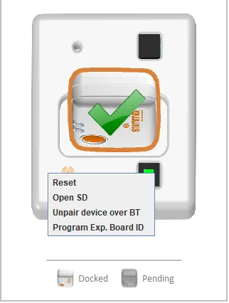
Figure 6‑13 The Shimmer right-click menu option as accessed via the Manage Devices tab in Consensys v1.5.0 or greater.
Select the right click menu option titled “Program Exp. (Expansion) Board ID”.
Select “Proto3 Mini (SR36)” from the drop-down menu, enter a Rev of “2” and click “OK”.
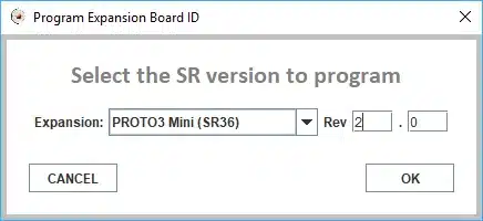
Figure 6‑14 The Consensys dialog which allows the customer to program the Expansion Board ID in the Shimmer3.
To return the Shimmer to normal operation if the Proto3 Mini is disassembled from the IMU, repeat the procedure but instead select the option “Shimmer3 (SR31)” from the drop-down menu and a Rev of “7”.
7. Troubleshooting
7.1. Secure connection between Shimmer and expansion board
Shimmer recommends an adhesive to secure the connection between the Shimmer3 mainboard and Expansion Boards. The adhesive that is used by Shimmer during assembly is called Superdots (www.superdots.com). We use the Ultra Tak variety. With Superdots applied, the expansion boards can still be removed and swapped out, if required, as the adhesive does not go solid but has a rubbery consistency, allowing it to be removed. However, customers should remember that frequently removing expansion boards is not recommended and can cause damage to the connectors. Superdots also provides some shock absorbtion.
Shimmer fits the Superdots by stretching them around the edges of the Expansion Board. This ensures that the adhesive doesn’t prevent the connectors from making a good connection and there is enough adhesive to secure the boards together but not to interfere with the fit.
Note: Shimmer does not supply Superdots.
Legal notices
Legal Notices and Disclaimer
Redistribution IS permitted provided that the following conditions are met:
Redistributions must retain the copyright notice, and the following disclaimer. Redistributions in electronic form must reproduce the above copyright notice, this list of conditions and the following disclaimer in the documentation and/or other materials provided with the document.
Neither the name of Shimmer Research Ltd. nor the names of its contributors may be used to endorse or promote products derived from this document without specific prior written permission.
THIS DOCUMENT IS PROVIDED BY THE COPYRIGHT HOLDERS AND CONTRIBUTORS “AS IS” AND ANY EXPRESS OR IMPLIED WARRANTIES, INCLUDING, BUT NOT LIMITED TO, THE IMPLIED WARRANTIES OF MERCHANTABILITY AND FITNESS FOR A PARTICULAR PURPOSE ARE DISCLAIMED. IN NO EVENT SHALL THE COPYRIGHT OWNER OR CONTRIBUTORS BE LIABLE FOR ANY DIRECT, INDIRECT, INCIDENTAL, SPECIAL, EXEMPLARY, OR CONSEQUENTIAL DAMAGES (INCLUDING, BUT NOT LIMITED TO, PROCUREMENT OF SUBSTITUTE GOODS OR SERVICES; LOSS OF USE, DATA, OR PROFITS; OR BUSINESS INTERRUPTION) HOWEVER CAUSED AND ON ANY THEORY OF LIABILITY, WHETHER IN CONTRACT, STRICT LIABILITY, OR TORT (INCLUDING NEGLIGENCE OR OTHERWISE) ARISING IN ANY WAY OUT OF THE USE OF THIS DOCUMENT, EVEN IF ADVISED OF THE POSSIBILITY OF SUCH DAMAGE.
